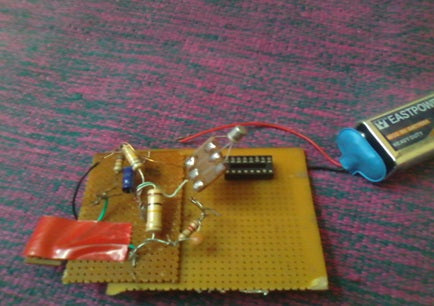
The proposed simple electronic spy Bug circuit is basically a high gain amplifier using IC 741 as the heart of the circuit and also some high gain output transistors. The IC 741 is configured as a non-inverting amplifier that performs the function of a pre-amplifier stage. The gain of this IC 741 preamplifier stage can be varied as desired by using the potentiometer on its input and output pinouts.
The gain setting is used to set the sensitivity of the amplifier and is set to maximum so that even low-volume voice conversations can be picked up through it. The microphone at the input transforms the sound vibrations into tiny electrical pulses, which are further amplified by the IC 741 to suitable levels before applying them to the output amplifier stage consisting of a standard DARLINGTON stage. This Darlington stage is made using some bc107A high gain transistors.
.Here the signal received from output 741 is suitably amplified so that it is finally sent to the headphone or antenna. Here I showed for the antenna that we can use the headphone output as well. we can worry about the external nine volts supplied to the circuit to make the signal powerful on the input side as well as the output side. If that doesn't work, use a 20k pot on R1. Here in the circuit I used a transistor which is also efficient to work.


Conclusion :
The result can be found on the radio as we set the frequency or search for the signal. Here the signal can be stronger if we use the shorter antenna. This may be more sensitive if you don't solder the microphone and it works, you may hear it in a low tone.
Calculations:

Set the required value for the transmission frequency
So, for example:
For F=100.5 Mhz and let's take L1=22nH
So we have the capacitance value as 1000uF
So resolve everything the best!!!
CIRCUIT DIAGRAM :
Parts list for the above op-amp based spy bug
R1 = 10K,
R3, R4 = 27K,
R4= 1.5M,
R5 = 50K,
C1 = 104,
C2 = 220uf/25v,
T1 = BC107A,
T2 = BC107A,
L1=22nH
MIC = electret microphone,
IC1 = 741,
Power = 9 volt battery
Circuit diagrams
| Circuit-Diagram-FM-Transmitter-Bug |  |

