Controlling LED brightness or dimming an LED using 8051(89c51,89c52) microcontroller is not an easy task. In-depth knowledge of 8051 microcontroller timers and their registers is required to dim or control LED brightness with 89c51 microcontroller. So in this project/tutorial I will teach you how to fade an LED with an 89c51 microcontroller?
|
How to control LED brightness?
To fade and control the brightness of the LED, we have to provide different voltage signal levels to the LED. Each voltage level glows according to the voltage value. For example, you have an LED whose rating is 5 volts. To fade we have to supply voltage ranging from 0.1 to 5 volts. At 5 volts, the input LED will shine at maximum brightness. Decreasing the voltage by 5 will decrease the LED brightness. If we speed up the glow cycle, the LED will show a fading effect.
|
Typical LED Brightness Control Method
A variable resistor can easily fade an LED by varying the resistance, if the LED is connected in series with it. Changing the resistance increases or decreases the output voltage. In the same way we turn the fan's potentiometer/variable resistor to speed up or slow down the rotation speed of the domestic ceiling fan. With a variable resistor/potentiometer, it is easy to control the brightness of the LED. But when we need to control the brightness with the microcontroller, it seems to be a difficult task as there is no variable resistor functionality in the microcontroller.
How to fade the LED using microcontrollers?
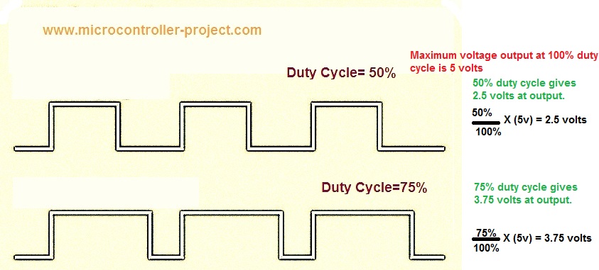
The best way to dim LED using microcontrollers is to use PWM (Pulse Width Modulation) technique. In pulse width modulation, the duty cycle of the signal is varied. The duty cycle is the ratio between the active period and the non-active period. For each duty cycle, the output voltage is different. 100% duty cycle provides maximum tension. When the duty cycle decreases from 100%, the output voltage also decreases. Here is a simple image that clarifies the duty cycle game.

PWM duty cycles
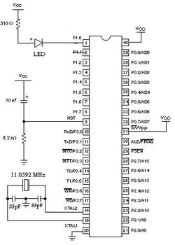
89c51 LED Fading Circuit Diagram
I connected the LED to pin no. 0 of port 1 of the 89c51 microcontroller. The LED is connected in series to a 510 ohm resistor. The 11.0592 MHz crystal is used to supply clock to the 8051 microcontroller. The Crystal is connected to the 8051 microcontroller in parallel to two 22pf capacitors. The circuit diagram of the project is given below.

LED fading using PWM technique with 89c51 microcontroller
PWM (Pulse Width Modulation) Signal Generation Using 89c51 Microcontroller Timers
To generate PWM using a microcontroller, it is necessary to use its timer. In the code below I used timers to generate PWM. The 8051 series microcontrollers have two built-in timers. You can use them as 16-bit or 8-bit. Since 8051 is an 8-bit microcontroller, how could we use the timer in 16-bit mode. There are two dedicated 8-bit registers for timers. You can combine them to use the timer in 16-bit mode. These registers are THx and TLx. To learn more about 8051 timers, the registers associated with them and how to use the timers just follow a short tutorial.
How to use internal timers of 8051 microcontroller(89c51,89c52)?
I am using Timer-0 of 89c51 microcontroller in 16-bit mode. They are two most important variables in my code. They are high-low and h1-l1. high-low is associated with the high period of the signal and h1-l1 is associated with the low period of the signal. high and h1 are associated with the TH0 record of 89c51. I'm generating 20 different waves to achieve PWM. 20 different waves means 20 different work cycles. In the code, a for loop is executed 20 times, the work cycle logic is placed in this for loop. Initially, the duty cycle is low for a small period and then increases increasingly up to 100%. In fact, timers are loaded with 20 different values and work with 20 different values, but at the same time the timer works with a single value.
In the code initially TH0 is loaded with 0xFF(high) and TL0 with 0xFF(low), this combination is for a high signal. The timer works with this combination 100 times and at the same time for low signal TH0 is loaded with 0xEB(h1) and TL0 0xFF(l1). TH0 is loaded with 0xEB because we initially want low signal for a long period. Now, when this loop runs, the signal for high waves increases and the signal for low waves decreases. Due to which we receive a PWM signal as output on the pin and we can see the LED fading and brightness increasing and decreasing continuously.
Note : 0xEB gives a gap of 0xFF-0xEB(hexadecimal)=20(decimal). Therefore, we are increasing and decreasing our signal levels equally on both sides (high and low). h1 increases from 0xEB and goes to 0xFF after 20 increments and high decreases from 0xFF to 0xEB after 20 decrements. You can increase the PWM frequency by using a high value crystal.
Download the project code and HEx file. The code is written in C language and keil compiler is used to compile the code. The folder also contains the project simulation. The simulation is done in Proteaus 8.0. Please give us your feedback on the project.
Fading Led with 89c51 microcontroller


