The counter is bidirectional, meaning it can count/increment if the object crosses its barrier in the left or right direction. The basic idea behind this is that you don't need to manually count people, people, vehicles, etc., passing by a certain location.
|
The initial counting starts through Babbage and then number counting was invented, then people started counting things manually. Now it is the digital age and we count things digitally. Previously, in manual counting, there were problems. You have to stand still for hours to count people and vehicles passing through a certain area, you can also lose data if your attention turns elsewhere. This project is the best example of precision and labor reduction in extra counting tasks.
|
Digital counter project requirements
- 8051 Microcontroller (89c51 or 89c52)
- LCD 16×2
- crystal (11.0592 MHz)
- LDR (Light Dependent Resistor)
- 5K resistor
- Breadboard or PCB for circuit design
- Power supply
- Potentiometer (to see the LED contrast)
-
Connecting wires
Some tutorials related to the project. As the 16×2 LCD interfaces with the 89c51 microcontroller, it works on operational modes and commands. The tutorials will help you understand the code below.
Commands and data sent to 16×2 LCD – Difference
Object/person counter with 89c52 microcontroller – Circuit diagram
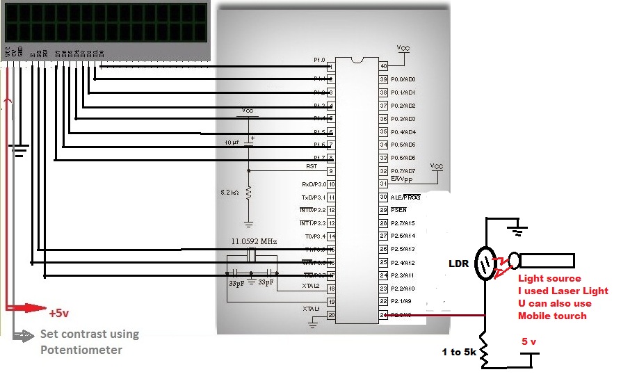
Counter values are displayed on a 16×2 LCD. The LCD is interfaced with the 8051 microcontroller in 8-bit mode. The 16×2 LCD data pins are connected to Port 1 of the 8051 microcontroller (89c51 or 89c52). The rs (register select) pin of the 16×2 LCD is connected to port 3, pin 5 of the 8051 microcontroller. The rw (read-write) pin of the LCD is connected to the port 3, pin 7 of the 8051 microcontroller. (enable) of the LCD is connected to pin 6 of port 3 of the 89c51 microcontroller. The rest of the connections are used to make the 8051 (89c51 or 89c52) microcontroller operational. How to apply 5v to vcc (pin 40) and vpp (pin 31). Ground pin 20. Connect the crystal to pins 18 and 19. 11.0592 MHz crystal is used in the design.
digital counter sensor 89c51
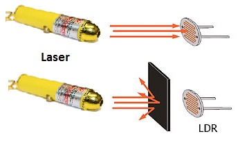
There are several techniques and pre-assembled sensors available on the market for counting purposes. The most popular technique among DIY embedded circuit designers is to use laser light and a light-dependent resistor (LDR). Laser light is fired at a distance into a light-dependent resistor. When a person passes between the laser setup and the LDR, the light stops falling on the LDR. Movement when the person is in front of the laser light blocks the light and the LDR laser light connection is braked. The connection is made again when the person moves away from the laser light. This interruption and establishment of the connection is interpreted by the 8051 microcontroller and is counted as 1.

Laser object and LDR (light dependent resistor), people, people, vehicle counter
The last thing in the circuit is pin 0 of Port-2. Here all the logic is created. The laser light continuously falls on the LDR (light dependent resistor), causing a short circuit in the circuit. The controller read as '0' or low. Now when someone passes by the path and cuts the laser falling on Ldr. The circuit is completed and the controller reads as '1' or high. Therefore, whenever the light falling on the LDR is disturbed, the controller reads it as 1 and increases the output.

Door, people, people, vehicle counter with 8051 microcontroller circuit diagram
Microcontroller Object Counter Code 8051
The code is simple, first I include the necessary header file registry<51.h> . If you are coding in keil ide for 8051 microcontroller, this library must be included in your source code. Then conditions check function is initialized. This function checks whether the person is in the path or not. Then single sbits are set to activate, select register and read write pins of 16×2 LCD. Variable count is initialized to connect our logic circuit to port 2 pin 0. Delay The function is generating some delay to be used when necessary. lcdcmd The function is sending commands to the lcd. data lcd function is sending data to lcd. lcdint is initializing the lcd. Then finally the main function is defined.
When you have finished creating the circuit and writing the hexadecimal code into the microcontroller, now it is time to see the result. When starting the program you will see the text “ DOOR COUNTER!!! ”Displayed on the first line of the 16×2 LCD. In the second line there is nothing. Now move your finger and cut off the light falling on the light dependent resistor. You will see the number displayed on the screen and every time you turn off the light, the number will increase by one.
More counter and security alarm projects using different microcontrollers and sensors like PIR (passive infrared), LDR (light dependent resistor), laser light, ultrasonic sensor etc.
Home security with Arduino Uno
PIR security system over WiFi using nodemcu
Watch the project video here……..
Port counter files/code


