Automation applications often require controlling multiple actuators (such as many motors) at the same time. For simultaneous and synchronous control of many actuators, they need to be controlled and operated independently. Engineers use as many controllers (microcontrollers or ASICs) as the number of actuators needed to operate independently. However, when a controller is capable of operating multiple actuators (which is possible when it has a large number of input/output pins) and has a high clock speed (where, due to the high clock speed of the controller, the actuators appear be controlled independently at the same time), it is preferable to use a single controller to manage multiple actuators. This reduces the size and complexity on the hardware side, reducing the overall cost of producing the specific embedded system. However, such a system requires complex software installed inside the controller.
In this project, a general-purpose embedded application was designed to control 32 servo motors (independently and simultaneously) by the popular ATMega32 AVR board. A complex C program is designed here to move 32 servos at predetermined speeds to positions predefined by the ATMega32.
The servos can move to 10 different positions (ranges) within 20 milliseconds. They occupy each position within a sub-period of 2 milliseconds, i.e., to assume a predefined position, they take a maximum of 2 milliseconds or less. The set of these preset positions (10 individually defined positions for 32 servos) continues to repeat at 20 millisecond time intervals until the system remains on. Within each 2 millisecond subinterval, the servos move to the preset position and remain there until the 2 millisecond subinterval is completed. To do this, they are stopped at specific moments of time (which are obviously always 2 milliseconds or less). Similarly, one servo can reach and rest in its preset position in 1.2 milliseconds and another can reach and rest in its preset position in 1.5 milliseconds. The servos continue receiving PWM pulse until they have to be moved and then when they need to be stopped at a pre-defined position (within the 2 millisecond sub-range), the PWM pulse stops.
Servos can assume up to 100 different preset positions in each 2-millisecond subinterval. Suppose a servo can rotate from 0 to 180 degrees by providing a PWM signal of 1 millisecond to 2 milliseconds, then it can move to 100 positions with a difference of 1.8 degrees each.
By reaching each position (range) within a 2 millisecond subinterval, the servos can reach preset positions at different speeds. For speed variation, temporary positions are defined in the code where the PWM pulse is stopped for 10 microseconds. The greater the number of temporary positions (10 microsecond steps or dead zones), the lower the rotation speed. However, the servo will reach the preset position within a sub-interval of 2 milliseconds. If there is only a temporary position set to reach the preset position, the servo will rotate at its maximum rotational speed (as a continuous PWM pulse will be supplied to it) to reach that preset position (angle) and will stop when it reaches its position preset. position (range) at an instant of time within a 2 millisecond subinterval. If there are 10 temporary positions set to achieve the preset position (angle), there will be 10 steps or 10 microsecond dead zones, which will reduce the servo rotation speed accordingly. In this way, there is speed variation where the servo rotates at its maximum speed to the predefined position when there is 1 step (or dead zone or temporary position) and rotates slowly as there are more steps (up to 10).
This is similar to industrial automation applications and can be used to control robotic arms or wings of a drone. The C program presented here is a general-purpose program that can be modified by coding the speed and position values of individual servos to suit any type of automation application. The C program presented here was developed and compiled using AVR Studio.
A modification of the above design is also provided where 30 servos are controlled (by 30 input/output pins of the AVR ATMega32) and 2 input/output pins are used for serial communication with an external device. Here the external device connected via UART sends the values to the ATMega32 to control and change the servo sequence in real time. The external device (another controller or PC) can be connected via RS-232, Bluetooth or any interface using the UART protocol.
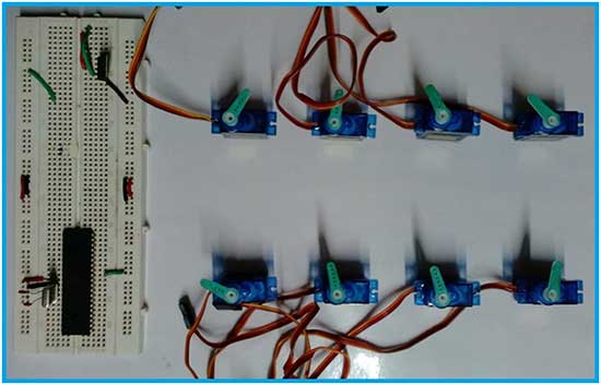
Fig. 1: Multiple Servo Controller Prototype based on AVR ATmega32
Required components –

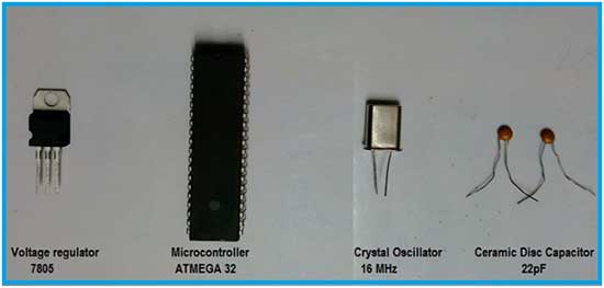
Fig. 2: Image of components required for the ATmega32 AVR-based multiple servo controller
Circuit Diagram –
The servo motor controller for 32 servos has the following circuit diagram –
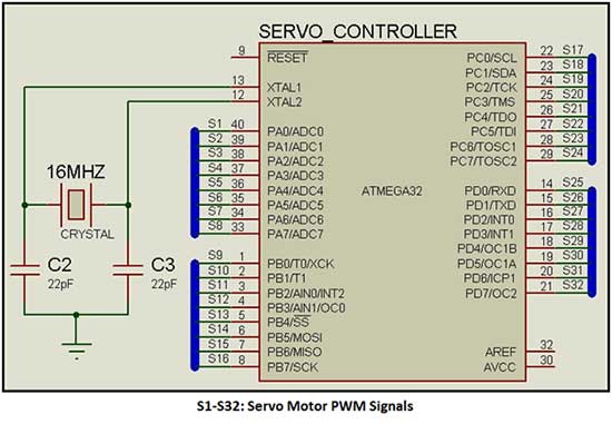
Fig. 3: Circuit diagram of AVR-based multiple servo controller ATmega32
The servo motor controller for controlling 30 servos with UART serial communication for remote operation by external device has the following circuit diagram –
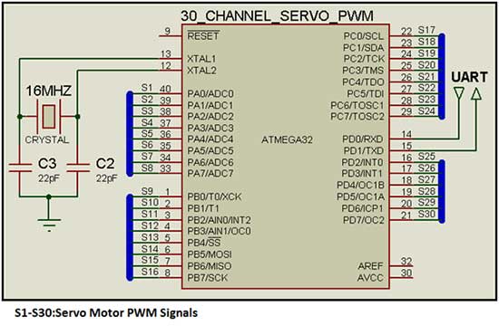
Fig. 4: Circuit diagram of AVR-based multiple servo controller ATmega32
Circuit Connections –
The circuit used in this servo motor controller is very simple. A servo motor has three terminals – VCC, Ground and Signal. The VCC pin is connected to 5V supply and grounded to common ground. The servo signal pin is connected to the GPIO of the controller to provide PWM signal. The servos used in this circuit are SG90 which can rotate 180 degrees (90 degrees in any direction). By providing 1ms high pulse, the servo rotates to -90 degrees. By providing 1.5ms high pulse it moves to 0 degree and by providing 2ms high pulse it moves to 90 degrees. So for a PWM input of 1 ms to 2 ms, the servo rotates from -90 degrees to 90 degrees.

Fig. 5: Servo motor pin diagram
The AVR ATMega32 has 32 general-purpose input/output pins from which the PWM signal can be supplied to 32 servos. It comes in a 40-pin PDIP or 44-pin TQFP/MLF package. The 40-pin PDIP package is used because the circuit is designed on a breadboard. AVR ATMega32 has the following pin diagram –
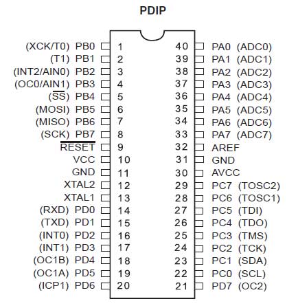
Fig. 6: AVR ATMega32 pin diagram
The servos are connected in alphabetical order of ports as follows –
PORT: S1-S8
PORTOB: S9-S16
PORT: S17-S24
PORT: S25-S32
For high operating speed, the maximum frequency is selected for the AVR. A 16 MHz crystal oscillator is connected between pins 12 and 13. Two 22pF capacitors are used to resonate with the crystal inductance which are connected in series to ground.
The servos as well as the ATMega32 are supplied with 5V DC for operation. The circuit's DC power supply is chosen taking into account the total current consumed by all servos connected to the AVR. The rated current of the DC source must be greater to support the peak load currents of all servos. A rule of thumb for finding peak load current for standard servos is 1A for 3 to 4 Kg servos. The SG90 servos used in this circuit weigh 14.7 g (Source – SG90 Servo Datasheet). Therefore, each servo draws maximum current of about 15 milliamps. The ATMega32's PDIP package consumes 200 milliamps of current. Therefore, the total current requirement can be calculated by adding the maximum current drawn by all the servos and the AVR controller as follows –
Total Current = Current consumed by the AVR ATMega32 + Current consumed by the Servos
Total Current = 32X15 mA + 200 mA
Total current = 680 mA
Therefore, DC power must be 5V and at least 680 mA.
In the remotely operated version of the circuit, two servos are removed from pins 14 and 15 and an external device (controller or PC) is connected to the ATMega32 via UART.
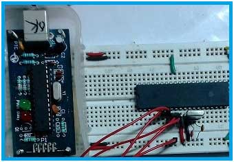
Fig. 7: Image showing the controller circuit of the multiple servo control based on AVR ATMega32
How the circuit works –
The servo motor controller designed here has a predefined set of servo positions (10 positions per servo) in the firmware code. When the circuit is turned on, the controller reads a matrix where the current position, end position and rotational speed of each servo are predefined. Consequently, the time instants within the first 2 millisecond subinterval for each servo to stop are determined. The time instants to stop the servos are sorted in ascending order and the time instant with the smallest value is loaded into the comparison register of a timer. PWM pulses are activated for all servos. The PWM signal for each servo is turned off as the respective timer interrupt is generated. The maximum PWM signal width can be 2 milliseconds. The servos rotate to their preset position (track) and stop to rest in that position. Each servo has its own end position (angle) and speed (determined by the number of dead zones or temporary positions defined for that servo). Once the 2 millisecond subinterval is complete, all servos have reached and stopped at their first preset positions. The current new servo positions are updated in the controller. The final positions of the first cycle now become the current positions of the second cycle.
Now the final positions and velocities for the second 2 millisecond subinterval are loaded into the matrix. Consequently, the time instants within the second 2 millisecond subinterval for each servo to stop are determined. Again, the time instants to stop the servos are sorted in ascending order and the time instant with the smallest value is loaded into the timer comparison register. PWM pulses are activated for all servos. The PWM signal for each servo is turned off as its respective timer interrupt is generated. This repeats for each of the remaining eight 2-millisecond subintervals.
Once the 10 cycles (2 millisecond subintervals) are complete, the 20 millisecond loop will complete. Now again, the loop starts at the first 2 millisecond subinterval and continues for the remaining cycles. The loop of 10 cycles for 10 preset positions for each servo continues to repeat until the system remains on. If the system is turned off and restarted, the 10 cycle cycle starts from the first cycle.
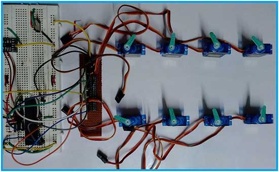
Fig. 8: Image showing the operation of the multiple servo control based on AVR ATMega32
Programming guide –
The firmware of this servo motor controller was developed in embedded C for AVR ATMega32. To write and compile code, winavr and programmer's notepad are used.
The operation of this circuit is based on timer interrupts. The AVR ATMega32 has three timers – Timer0 (which is an 8-bit timer), Timer1 (which is a 16-bit timer), and Timer2 (which is an 8-bit timer). Timer1 and Timer2 are used in coding this system.
Timer1 is a 16-bit counter formed by two 8-bit registers – TCNT1H and TCNT1L. It is used to count time and generate interruptions at the desired instants of time to turn off the respective servo pulses. Timer1 can operate in five modes –
1) Normal Mode
2) Clear timer in Compare Match (CTC) mode
3) Fast PWM mode
4) PWM mode with phase correction
5) PWM mode with phase and frequency correction
Here, Timer1 is operated in CTC (Clear Timer on Compare Match) mode.

Fig. 9: Bit values of the TCNT1 register on the AVR ATMega32
The following registers are associated with Timer 1 –
1) TCCR1A (timer/counter control register 1 A)
2) TCCR1B (timer/counter 1 control register B)
3) TCNT1 (Timer/Counter Register 1, is 16 bits – TCNT1H and TCNT1L)
4) OCR1A (1 A output comparison register, is 16 bits – OCR1AH and OCR1AL)
5) OCR1B (Output comparison register 1 B, is 16 bits – OCR1BH and OCR1BL)
6) ICR1 (Input Capture Register 1, is 16 bits – ICR1H and ICR1L)
7) TIMSK (Timer/Counter Interrupt Mask Register)
8) TIFR (Timer Interrupt Signaling Register)
Timer 1 has two control registers – TCCR1A and TCCR1B. It has a Flag – TIFR register that informs the controller of the status of Timer 1. TCCR1A is an 8-bit register with the following bit values –

Fig. 10: Bit values of the TCCR1A register on the AVR ATMega32
TCCR1B is also an 8-bit register with the following bit values –

Fig. 11: Bit values of the TCCR1B register on the AVR ATMega32
To set Timer1 in CTC mode, WGM13 and WGM12 in TCCR1B must be 0 and 1 respectively, while WGM11 and WGM10 in TCCR1A must be 0.

Figure 12: Table showing conditions for selecting CTC mode for timer 1
Furthermore, as a 16 MHz crystal oscillator is connected to the ATMega32, the time period of the crystal oscillator is as follows –
Time Period = 1/Frequency
= 1/(16X10^6)
= 0.0625 microsecond
With this F_CPU in normal mode, Timer1 could only count 4.096 milliseconds to full scale (0.0625 microseconds X 2^16). Therefore, it needs to be pre-scaled. The prescale is determined by bits CS12, CS11 and CS10 of the TCCR1B register according to the following table –
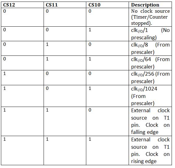
A value of 0x0A is written to TCCR1B while TCCR1A is left at 0x00. This sets Timer1 to CTC mode, making WGM13, WGM12 on TCCR1B 0 and 1 respectively, while WGM11 and WGM10 on TCCR1A 0. This also selects a /8 clk I /O prescaler. Therefore, Timer1 has a clock speed of 2 MHz (16/8). Each timer count now corresponds to the time period calculated below –
Time Period = 1/Frequency
= 1/(2X10^6)
= 0.5 microsecond
Now Timer1 can count up to 32.768 milliseconds (0.5 microseconds X 2^16). To generate interrupts within the 2 millisecond subinterval, it only needs to count to 4000 (0.5 microseconds X 4000 = 2 milliseconds). When the TCCR1B register is written with non-zero clock prescaler bits, the timer/counter is started. Therefore, this register is written after sorting and writing the minimum position values to the 16-bit Output Compare Register (OCR1A).
ATMega32 has TIMSK register which has interrupt control bits for all its timers/counters including timer 1. TIMSK has following bit values –

Fig. 13: Bit values of the TIMSK register on the AVR ATMega32
Bits TICIE1, OCIE1A, OCIE1B, and TOIE1 of the TIMSK register are associated with Timer 1. TIMSK is set to 0x90, which sets OCIE2 and OCIE1A to 1. Setting OCIE1A to High enables the output compare match interrupt of Timer/Counter1. . The time instant to stop the PWM signal is loaded into register OCR1A. When the TCNT1 count matches the value loaded in OCR1A, an interrupt is generated. Each time the interrupt is generated, the PWM signal to the respective sevo is turned off.
Timer2 is an 8-bit register (TCNT2) that is used to generate interrupts every 2 milliseconds (to indicate the end of 2-millisecond subintervals). It can operate in four modes –
1) Normal mode
2) Clear timer in Compare Match (CTC) mode
3) Fast PWM mode
4) PWM mode with phase correction
To enable Timer 2, OCIE2 was set to 1 in the TIMSK register. Timer 2 has the following registers associated with it –
1) TCCR2 (timer/counter control register 2)
2) TCNT2 (timer/counter register 2)
3) OCR2 (Output Comparison Register 2)
4) ASSR (Asynchronous Status Register)
5) TIMSK (Timer/Counter Interrupt Mask Register)
6) TIFR (Timer Interrupt Signaling Register)
Timer 2 is controlled by register TCCR2. TCCR2 has the following bit values –

Fig. 14: Bit values of the TCCR2 register on the AVR ATMega32
A value of 0x0D is written to TCCR2. The Timer 2 operating mode is selected by writing to bits WGM21 and WGM20 of TCCR2. Mode selection is done as per the following table –

When writing 0x0D to TCCR2, WGM20 is set to 0 and WGM21 to 1, so Timer 2 operates in CTC mode. As done for Timer 1, pre-scaling is also done for Timer 2. For Timer 2, pre-scaling is determined by bits CS22, CS21 and CS20 of the TCCR2 register according to the following table –
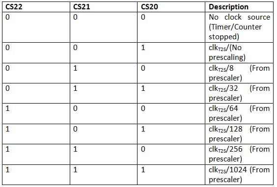
When writing 0x0D to TCCR2, CS22, CS21 and CS20 of TCCR2 are set to 1, 0 and 1 respectively. Therefore, Timer2 has a clock speed of 125 KHz (16/128 MHz). Each timer count now corresponds to the time period calculated below –
Time Period = 1/Frequency
= 1/(125X10^3)
= 8 microseconds
For 2 milliseconds, timer 2 now needs to count to 250 (8 microseconds x 25
0 = 2 milliseconds). Therefore, a value of 250 is written to OCR2. When Timer 2 counts up to 250 and matches the value written in OCR2, the interrupt is generated. This indicates the end of a subinterval (one of ten cycles for servo positions).
The TIFR register has the following bit values –

Fig. 15: Bit values of the TIFR register on the AVR ATMega32
Timer 1 in CTC mode is comparing with register OCR1A. When generating interrupt, OCF1A in TIFR is set to High. When checking the status of OCF1A in TIFR, the interrupt generated by Timer 1 is monitored. Timer 2 in CTC mode is comparing with the OCR2 register. When this generates interrupt, OCF2 is set to High. When checking the status of OCF2 in TIFR, the interrupt generated by Timer 2 is monitored.
The C code developed for this AVR circuit follows an algorithm summarized by the following flowchart –
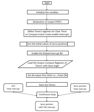
Fig. 16: Flowchart of the algorithm used by the AVR code to control multiple servos
Code C follows the following algorithm –
1) Load and classify the servo positions (angles) for the first 2 millisecond subinterval –
For the first 2 millisecond subinterval, the current position, end position, and rotational speed of the servos are stored in a two-dimensional array servo_positions(ns+1)(3) . The array is sized by one unit larger than the number of servos connected to the AVR ATMega32. Since there are 32 servos connected to the controller, the constant ns is initialized to 32.
The array stores three bytes for each servo. The first byte is the speed value, the second byte is the end position (end angle) of the servo, and the third byte is the current position (current angle) of the servo.
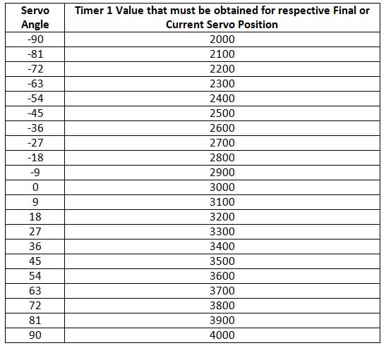
The end positions are mentioned as values that must be loaded into Timer 1 to stop the PWM signal when the Timer 1 interrupt for the respective servo is generated. The servo rotates to -90 degrees when a 1 ms PWM pulse is supplied to it. It rotates to 0 degrees when 1.5 ms PWM pulse is supplied and rotates to 90 degrees when 2 ms PWM pulse is supplied. For a PWM signal of at least 1 ms, Timer 1 needs to count to 2000, as 2000 Timer 1 counts are equivalent to 1 millisecond in its control register settings. Thus, the final and current positions of the servos can be between 2000 and 4000 as the PWM signal of minimum 1 millisecond and maximum 2 milliseconds can be provided to rotate the servo between -90 to 90 degrees. Any value, for the current and final position of the servos, less than 2,000 or greater than 4,000, is therefore irrelevant. Therefore, the final and current position of the servo must always be set between 2000 and 4000.
The code was developed to rotate the servo in 100 different positions (angles) between -90 and 90 degrees. All adjacent positions are spaced 1.8 degrees apart from the servo angle. Since the Timer 1 count for each servo position can be between 2000 and 4000, with 100 possible positions (angles), the Timer 1 count is incremented by a factor of 20 for any next servo position (angle). For example, to move the servo to the end position of -90 degrees, the end position defined in the code must be 2000. To move the servo to a higher position, i.e. -88.2 degrees (-90+1.8 degrees), the final position defined in the code must be 2020 and so on. The end or current position values required to rotate the servos by some standard angles are listed in the following table –
The speed is controlled by the first byte of the servo_positions(ns+1)(3) array. The value mentioned in this variable defines the number of temporary angles that are reached before reaching the final angle (final position). A 10 microsecond dead zone (equivalent to Timer 1's count of 20) is inserted after each temporary position. For each servo that is to be stopped next, the value at the respective index in cycle_speed(temperature) array is reset to 0 and compared to the speed value in servo_positions(ns+1)(3) array in a while loop. The value of the speed_cycle variable is incremented at each temporary position and compared with the speed value of the servo_positions(ns+1)(3) range. Once the value of respective index in cycle_speed(temperature) array becomes equal to the speed value of servo_positions(ns+1)(3) array, the final position is reached. The speed value from servo_positions(ns+1)(3) array is used to assign value to another variable steps . The value assigned to steps is equal to the number of temporary positions. The difference between the end position and the current position is calculated and divided by steps to enter temporary positions before reaching the end position (angle). If the step value is 1, continuous PWM signal will be supplied to the servo without any dead zone, then the servo will rotate to the maximum speed to reach the end position from the current position. If the step value is larger, there will be the same number of temporary positions and dead zones before reaching the final position, so the rotation speed to reach the final position will be reduced accordingly. The step variable is initialized to 5, but for each servo position in each 2-millisecond subinterval, it is assigned equal to the respective speed value of servo_positions(ns+1)(3) array. The speed value should always be set to a positive integer ranging between 1 and 10 to avoid position errors such as negative values or out-of-range position values. Thus, a speed value of 1 indicates the highest rotational speed of the respective servo while a speed value of 10 indicates the lowest rotational speed of the respective servo.
1) Identification of unique time instants when one or more servos need to be stopped within a 2 millisecond subinterval –
The final positions of all servos are sorted in ascending order and the indexes corresponding to the servos that must be stopped one after the other are stored in an array defined as order(ns+1) . The size of the order array is one larger than the number of servants. Index 0 of the order array is not used.
There may be situations where two or more servos may have the same end position and need to be stopped at the same time. Thus, the difference between consecutive final positions after sorting is calculated in a loop and for each non-zero difference, a variable ' instants ' is incremented by one. This gives the exact number when the Timer 1 interrupt should be generated. The difference between consecutive finishing positions after sorting is stored in a Temp2 variable and its value is loaded into the OCR1A register. The end positions at which Timer 1 interrupts should be generated are stored in another array – timer_inst .
2) For each single time instant, generate Timer 1 interrupt and update the gate outputs –
For each instant, the port values (PWM signals from the GPIO pins) are stored in a Port_Values array. This way, if two or more servos have the same final position and must be stopped at the same instant of time, a single interrupt is generated at that instant of time by comparison with the values in the timer_inst array, and all servos with that final position are stopped where they interrupt (and at that instant) assigning to the ports the values stored for the respective index in Port_Values array. The respective port_value is written using a 'switch statement' in the code and this is repeated for all the servos.
The BIT Wise OR operation is used to repeatedly update the values in the ports_value array without changing the previous values. The bitwise AND operation with inverted port_value is used to turn off the pins (bits) that are HIGH in the port_values variable to stop the respective servo(s). All “port_values” are written and assigned to all PORTs at all times of the timer. Even though there is no port_value (zero) at any time for a given port, the PORT pins are not changed due to the inverted BIT Wise AND operation.
Initially, all PWM signals are turned ON and at least 1 millisecond of PWM signal is supplied. Then, the servos are stopped one after the other while their respective Timer 1 interrupt is generated within the 2 millisecond subinterval. At each interrupt, Timer 1 is cleared and loaded with the value of the difference with the next consecutive final position of the sorted array.
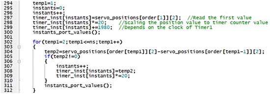
Fig. 17: Screenshot of the AVR code for controlling multiple servomotors
The final and current positions of the servos must always be between 2000 and 4000. This is why, for safety, the code is developed in such a way that the user must set a value between 0 and 100 for the final positions of the servos. The values entered for the end positions of the servos by the user are multiplied by 20 (unit defined to increment the count of Timer 1) and are added to 2,000 in the code to derive the actual interrupt instants of Timer 1. The values of the current positions and Ends of standard servo angles that are to be entered by the user in the servo_positions(ns+1)(3) and servo_tracks(10)(2)(ns+1) matrices are listed in the following table –
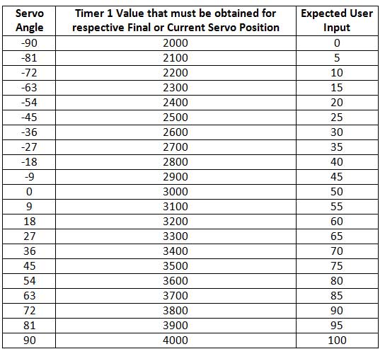
4) Repeat 2 millisecond subintervals 10 times and repeat the entire schedule infinitely –
Timer 2 is generating interrupt every 2 milliseconds. When it generates an interrupt, it is an indication that the current 2 millisecond subinterval has ended. All servos are then turned off (writing 0x00 to all ports) as a precautionary measure. The number of 2-millisecond subintervals is tracked by a cycles variable. This variable is also incremented by one when Timer 2 generates the interrupt.
When 10 2-millisecond subintervals have ended, a period of 20 milliseconds has passed. Since the servos are assumed to operate at the signal frequency of 50 Hz (1/50 = 20 milliseconds), the servo positions are now repeated from the position in the first 2 millisecond subinterval. This keeps repeating until the system stays on.
Note that in this circuit the PWM signals for 10 servo angle sequences for 32 servos are encoded in the firmware code. The end user does not always have access to the firmware code. Thus, a modification of the above circuit is also presented where 2 servos are removed at pins 14 and 15 and an external device (another controller or PC) can be connected to the ATMega32 via UART.
The modified circuit can receive values from external sources and operate servos in real time by a human operator. An interrupt subroutine ISR(USART_RXC_vect) is defined in the code to receive information from the external source. This ISR is commented out in the original code (where 32 servos are controlled). By properly laying out the sequential positions, complex sequences can also be pre-programmed. This is limited only by the microcontroller's RAM to store the data variables. The program presented here contains a 10-step sequential program, which swings the arms within pre-defined limits. This sequence is called track and the position along with the speed are defined in the track matrix (3-Dimensional). An external microcontroller can be programmed to pass the sequences in the predefined format according to real-time human input or the real-time human input can be passed through a terminal application on a PC in the predefined format.
UART is used to update the servos' positions in real time from the outside world. This will reduce the 32 channels to 30 channels as two pins TX and RX are used by UART for data processing. This is useful on multiprocessor systems. The main processor outputs data to this servo controller depending on real-time inputs or feedbacks. This is also useful for wireless control of servo motors using Bluetooth or any other wireless serial transmission.
Project source code
###
//Program to #include#include #include #define ns 32 #define nt 8 unsigned char servo_positions(ns+1)(3)= {{0,0,0}, //ns=no.of servos //Speed Final Position Present Position for initialization only {1,1,100}, {1,1,100}, {1,1,100}, {1,1,100}, {1,1,100}, {1,1,100}, {1,1,100}, {1,1,100}, {1,1,100}, {1,1,100}, {1,1,100}, {1,1,100}, {1,1,100}, {1,1,100}, {1,1,100}, {1,1,100}, {1,1,100}, {1,1,100}, {1,1,100}, {1,1,100}, {1,1,100}, {1,1,100}, {1,1,100}, {1,1,100}, {1,1,100}, {1,1,100}, {1,1,100}, {1,1,100}, {1,1,100}, {1,1,100}, {1,1,100}, {1,1,100}, }; unsigned char temp_servo_positions(ns+1),temp_inst=0,*temp_inst_addr=&temp_inst,step=5; unsigned char temp,temp1,temp2,temp3,swap,order(ns+1); unsigned char sorted_positions(ns+1),instants=ns,port_values(ns+1)(5), temp_port=1,cycles=0,speed=10,uart=0,track=0; unsigned int timer_inst(ns+1),speed_cycle(ns+1),sort=0; unsigned char servo_tracks(nt)(2)(ns+1)={ {//Speed //Position {0,1,2,3,4,5,6,7,8, 1,2,3,4,5,6,7,8, 1,2,3,4,5,6,7,8 , 1,2,3,4,5,6,7,8}, {0,100,100,100,100,100,100,100,100, 100,100,100,100,100,100,100,100, 100,100,100,100,100,100,100,100, 100,100,100,100,100,100,100,100}, }, { {0,1,2,3,4,5,6,7,8, 1,2,3,4,5,6,7,8, 1,2,3,4,5,6,7,8 , 1,2,3,4,5,6,7,8}, {0,1,1,1,1,1,1,1,1, 100,100,100,100,100,100,100,100, 100,100,100,100,100, 100,100,100, 100,100,100,100,100,100,100,100}, }, { {0,1,2,3,4,5,6,7,8, 1,2,3,4,5,6,7,8, 1,2,3,4,5,6,7,8 , 1,2,3,4,5,6,7,8}, {0,1,1,1,1,1,1,1,1, 1,1,1,1,1,1,1,1, 100,100,100,100,100,100,100,100, 100, 100,100,100,100,100,100,100}, }, { {0,1,2,3,4,5,6,7,8, 1,2,3,4,5,6,7,8, 1,2,3,4,5,6,7,8 , 1,2,3,4,5,6,7,8}, {0,1,1,1,1,1,1,1,1, 1,1,1,1,1,1,1,1, 1,1,1,1,1,1,1,1 , 100,100,100,100,100,100,100,100}, }, { {0,1,2,3,4,5,6,7,8, 1,2,3,4,5,6,7,8, 1,2,3,4,5,6,7,8 , 1,2,3,4,5,6,7,8}, {0,1,1,1,1,1,1,1,1, 1,1,1,1,1,1,1,1, 1,1,1,1,1,1,1,1 , 1,1,1,1,1,1,1,1}, }, { {0,1,2,3,4,5,6,7,8, 1,2,3,4,5,6,7,8, 1,2,3,4,5,6,7,8 , 1,2,3,4,5,6,7,8}, {0,100,100,100,100,100,100,100,100, 1,1,1,1,1,1,1,1, 1,1,1,1,1,1,1,1, 1,1,1,1,1,1,1,1 }, }, { {0,1,2,3,4,5,6,7,8, 1,2,3,4,5,6,7,8, 1,2,3,4,5,6,7,8 , 1,2,3,4,5,6,7,8}, {0,100,100,100,100,100,100,100,100, 100,100,100,100,100,100,100,100, 1,1,1,1,1,1,1,1, 1,1,1,1,1,1,1,1}, }, { {0,1,2,3,4,5,6,7,8, 1,2,3,4,5,6,7,8, 1,2,3,4,5,6,7,8 , 1,2,3,4,5,6,7,8}, {0,100,100,100,100,100,100,100,100, 100,100,100,100,100,100,100,100, 100,100,100,100,100,100,100,100, 1,1,1,1,1,1,1,1}, } }; void sort_positions(void); void instants_port_values(void); int main(void) { PORT=0; DDRA=0XFF; PORTB=0; DDRB=0XFF; PORTC=0; DDRC=0XFF; PORTD=0; DDRD=0XFF; sort_positions ; OCR2=250; OCR1AH=timer_inst(1)/256; OCR1AL=timer_inst(1)%256; temp_inst=1; PORT=255; //Turn ON All servo pulses PORTB=255; PORTC=255; PORTD=255; //Turn ON timers TCCR2=0X0D; //F/128,CTC Mode TCCR1B=0X0A; TIMSK =0X90; //OCIE 2.1A SREG =0X80; while(1); } ISR(TIMER2_COMP_vect) { cycles++; if(cycles==1) { //Precautionary:turn Off all pulses(servos) PORT=0X00; PORTB=0X00; PORTC=0X00; PORTD=0X00; //Server data update inquiry //uart=0; //do{}while((UCSRA&0X20)==0); //UCSRA =0X40; //UDR=0; //do{}while((UCSRA&0X40)==0); } else if(cycles==3) { //Server data update inquiry //uart=0; //do{}while((UCSRA&0X20)==0); //UCSRA =0X40; //UDR=1; //do{}while((UCSRA&0X40)==0); } else if(cycles==5) { //<2mS sort=ns; for(temp=1;temp<=ns;temp++) { if(servo_positions(temp)(2)>servo_positions(temp)(1)) { //1.5uS for one servo speed_cycle(temp)++; if(speed_cycle(temp)>=servo_positions(temp)(0)) { servo_positions(temp)(2)-=step; if(servo_positions(temp)(2) =servo_positions(temp)(0)) { servo_positions(temp)(2)+=step; if(servo_positions(temp)(2)>servo_positions(temp)(1)) { servo_positions(temp)(2)=servo_positions(temp)(1); } speed_cycle(temp)=0; } } else { sort--; //to count no.of unequal servo positions } } //Sorting-Ascending Order according to servo_positions(1) if(sort!=0) { sort_positions ; } else { track++; track%=nt; for(temp=1;temp<=ns;temp++) { servo_positions(temp)(0)=servo_tracks(track)(0)(temp); servo_positions(temp)(1)=servo_tracks(track)(1)(temp); } sort_positions ; } } else if(cycles==10) { PORT=0XFF; PORTB=0XFF; PORTC=0XFF; PORTD=0XFF; temp_inst=1; OCR1AH=timer_inst(temp_inst)/256; OCR1AL=timer_inst(temp_inst)%256; TCCR1B=0X0A; cycles=0; } } ISR(TIMER1_COMPA_vect) { TCCR1B=0X00; PORT&=~port_values(temp_inst)(1); PORTB&=~port_values(temp_inst)(2); PORTC&=~port_values(temp_inst)(3); PORTD&=~port_values(temp_inst)(4); if(temp_inst=1;temp2--) { swap=0; for(temp1=ns;temp1>=1;temp1--) { if(swap ###
Circuit diagrams
| Circuit diagram for independent multi-servo controller based on ATMega32 | 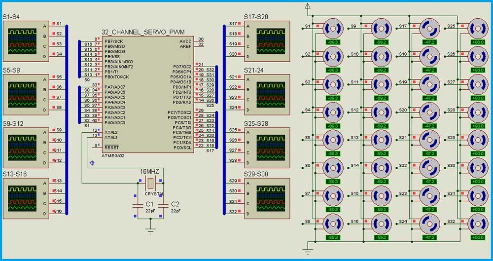 |

