
1. Cutting head introduction
Currently, the cutting heads used in the fiber laser cutting machine market are mainly the LightCutter (Figure 1) and ProCutter (Figure 2) series from PRECITEC, a German company.
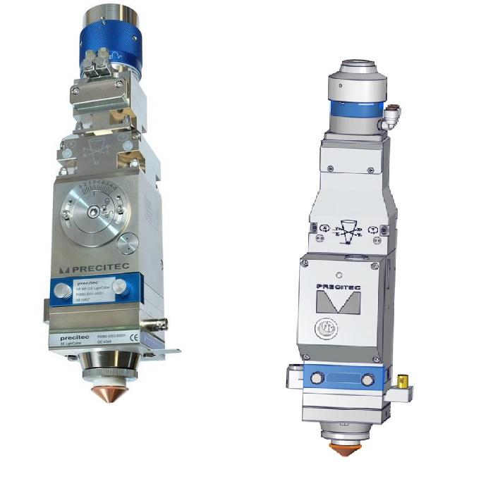
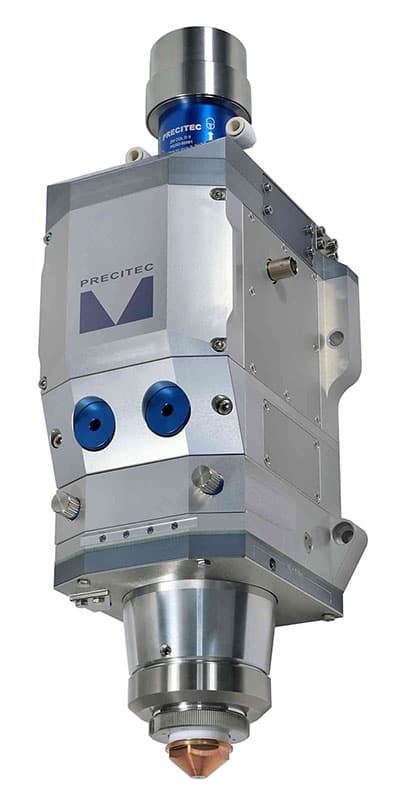
These two series of cutting heads are suitable for laser power in the following ranges: LightCutter≤2500W, ProCutter≤6000W.
2. Analysis of the Cutting Head Contamination Process
As shown in Figure 3, the optical components inside the cutting head consist of 2 collimating mirrors, 3 focusing mirrors, and 4 shielding mirrors. Pollution from these lenses directly affects the cutting process of the machine tool.
Based on long-term process testing and extensive customer usage analysis, the main factors causing cutting head pollution are as follows:
①Improper installation method of the optical fiber head.
②Poor sealing effect of the cutting head.
③Improper method of replacing protective mirrors.
④Unreasonable processing control time.
⑤Unscientific data of the cutting process.
⑥Use of low-quality vulnerable parts for the cutting head (protective mirrors, sealing rings, etc.).
⑦Improper operation and use by the end customer.
⑧Incorrect method of maintenance and repair of the cutting head.

- 1. Fiber optic connector
- 2. Collimation module containing two collimation mirrors
- 3. Focusing module containing two focusing mirrors
- 4. Protective window box
- 5. Sensor
- 6. Ceramic lock nut
- 7. Ceramic ring
- 8. Mouthpiece
- 9. Coaxial cable connector (transceiver cable connector)
Related Reading: Black Spots on Laser Cutting/Welding Lenses: Causes and Solutions Explored
3. Research on cutting head pollution prevention
Although it is challenging to achieve absolutely pollution-free cutting heads, there are methods that can be employed to prolong the time between pollution occurrences and reduce the severity of pollution. This can help increase the life of the cutting head and reduce maintenance and repair costs.
Addressing the factors listed above that contribute to cutting head pollution, respective measures can be taken as follows:
3.1 Improving the installation method of optical fiber head
Improvements can be made to the installation method by ensuring that the fiber optic head is inserted horizontally into the cutting head and locked securely.
It is important to maintain a clean environment during the installation process, and if there is a significant number of suspended particles (dust) in the surrounding area, it is recommended to carry out this task before 6:00 am, that is, before the installation begins. the work shift.
3.2 Improving the sealing effectiveness of the cutting head
Given the current level of mechanical manufacturing, even with the most advanced German technology, it is not possible to achieve absolute sealing for laser cutting heads. During subsequent use, it is inevitable that dust will enter and contaminate the lenses.
The main cause of this problem is the increase in cutting head temperature during the cutting process (normal cutting can be achieved when the cutting head temperature is <55°C).
This leads to an increase in internal pressure, causing some gases to be released from the cutting head into the surrounding environment.
When the cutting head stops working (after the work shift), the internal temperature drops to ambient temperature, resulting in the internal pressure being lower than ambient pressure.
Environmental gases contaminated with dust will then be drawn into the cutting head until the internal and external pressures reach equilibrium, thus polluting the cutting head.
To solve this problem, the approach is to maintain a positive pressure (greater than ambient pressure) inside the cutting head to isolate the ingress of dusty gases from the environment.
The following methods can be employed for improvement:
①Continuously supply clean, dry and oil-free gas to the cutting head. (Nitrogen is recommended, with a pressure of 0.15 bar ≤ P < 0.3 bar).
②Install a breathing system to always maintain positive pressure inside the cutting head.
3.3 Proper replacement of the protective lens
When replacing the protective lens, you need to do it quickly. While removing the protective lens window box (Figure 3), immediately seal the window to the cutting head with tape (sealing the protective lens window box installation opening).
Additionally, ensure that no dirty objects come into contact with the protective lenses and that operators avoid talking (to avoid splashing saliva on the protective lenses).
3.4 Rational Design of Machine Tool Control Timing
The propagation speed of light is faster than the transmission speed of gas. When cutting or drilling, there may be a delay in the cutting gas, causing the laser to begin processing before the cutting gas reaches the required pressure or flow rate, leading to contamination of the protective lens.
The following improvement methods can be implemented:
1. Modify the time of laser emission and gas release (gas cutting) by instructing gas release, waiting for a certain period (gas wait), emitting laser and then processing.
2. Maintain a certain air pressure (shielding gas) throughout the processing process.
The processing sequence must be as follows: instruct the release of the shielding gas, pre-process the plate (read the processing data and define the origin), instruct the release of the puncture gas, instruct the release of the puncture laser, instruct cutting gas release, instruct cutting laser release (cutting contour), complete contour cutting, quickly position for next contour, instruct puncture gas release, instruct punch laser release, instruct release the cutting gas, instruct the laser cutting release (contour cutting), complete the contour cutting, repeat the cycle, end the cutting process, turn off the shielding gas and end the program.
3.5 Data from the Rational Cutting Process
The use of rational cutting process data helps prevent the occurrence of contamination in the cutting head due to abnormal cuts.
3.6 Use of qualified consumables
The use of qualified consumables such as protective lenses and sealing rings contributes to the sealing of the cutting head.
3.7 Correct Operating Procedures
Follow the instructions provided by the equipment supplier to correctly operate and use the machine tool.
3.8 Suitable Maintenance Methods
Make sure the shaving head is clean and dry and clean it daily.
4. Conclusion
By implementing the above-mentioned contamination prevention methods, the contamination of the optical lenses inside the fiber cutting head is significantly improved.
Practical application has shown that with regular maintenance and careful attention to detail, frequent failures in cutting parts can be avoided, thereby extending the life of lenses and increasing the production efficiency of the equipment.


