In response to the problem of setting a reasonable and accurate machining scale for forgings in the CNC machining process, a method for directly forging transverse notches on forgings is proposed, which achieves accurate positioning of the CNC machining scale for forgings. This provides an effective solution as a reference for achieving rapid alignment of machining scales for forged parts.
0. Introduction
Due to the limited machining requirements of forging raw materials, structural characteristics require that the selection of CNC machining reference during the machining process of forging raw materials into parts is accurate. Otherwise, there will be deviations in the machining reference of forgings, resulting in insufficient machining tolerance for forgings and the phenomenon of insufficient raw materials that ultimately cannot be processed into parts. To solve this problem, the method of directly forging transverse notches on forged parts to calibrate CNC machining benchmarks can avoid such problems.
1. Basic design form of CNC machining as reference for forgings
The CNC machining scale for forgings refers to a specific symbol mark with identifying characteristics, which is forged on the surface of the forging and the forging at the same time, and is composed of two shapes below or above the surface of the forging. Symbol marking shapes mainly include cross lines, circles, triangles, T shapes and other types of structures. This article mainly introduces the CNC machining scale for forgings marked with “cross-section lines”.
2. Procedure for setting CNC processing date for cross-mark forgings
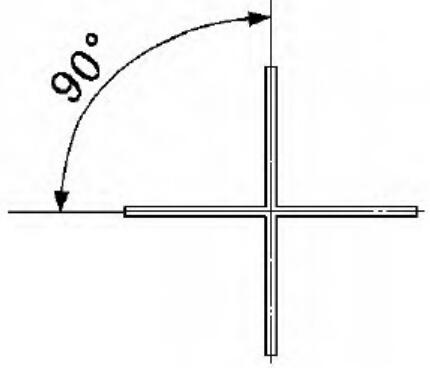
Clear, intuitive and easily recognizable markings are the standard of judgment for determining CNC machining benchmarks. The crosshair consists of two straight lines that intersect at 90° angles (see Figure 1), and the center of the crosshair intersection serves as the CNC machining reference point. The cross section is visually intuitive and clearly marked, making it easy to recognize and distinguish other surface features of the forging compared to other forms of identification. The two perpendicular straight lines of the cross-section line are parallel or coincide with the CNC machining coordinates of the X and Y axes (see Figure 2), so it is easy to see whether the forging orientation is correct, and the CNC machining benchmark can be quickly aligned to the forging. 
Figure.1 Cross line 
Figure 2: Intersection of the cross mark and machining coordinate system
2.1 Accurately setting a cross-marking reference on the surface of forgings
To set identification parameters accurately, the following aspects should be considered to reduce the accumulation of errors caused by multiple factors and achieve the goal of accurate identification and positioning.
2.1.1 Adoption of the principle of overlapping benchmarks
The cross-section line should preferably be in the position consistent with the reference hole to maximize the uniformity of the part design reference, forging reference and CNC machining reference (see Figure 3). If the three cannot be fully unified, it is necessary to ensure that the forging reference and CNC machining reference are unified. 
Figure 3: Overlay of basic design concepts, basic forging principles and basic CNC machining principles
2.1.2 Principle for optimizing the position of cross marking reference on the surface of forged parts
The location of the cross mark reference on the surface of forgings is shown in Figure 4. The principle of selecting the optimal position of the cross mark reference on the surface of forgings is as follows: the CNC machining reference coincides with the line connecting the centers of the two crossed marks. The CNC machining reference point coincides with one of the cross marks on two forgings and maintains the same distance from the other cross mark. Two cross-section marks cannot be in the same forging XY plane (on different step surfaces). 
Figure 4: Position of the reference cross on the forging surface
2.2 Use and size control of two different forms of cross-section markings
The cross mark consists of two forms: below (groove cross mark) or above (convex groove cross mark) the forging surface. Because double-sided machined forgings need to be marked with cross-section lines on both sides, the “groove cross-section line” is suitable for use on positioning reference surfaces and non-positioning reference surfaces; The “convex groove cross section” is suitable for use on non-reference surfaces.
The ultimate goal of cross-tagging is to facilitate detection by the human eye. In general, a cross mark can be set with length L = 30 mm, width E = 2 mm and depth H = 1 mm, as shown in Figure 5. 
Figure 5: Dimensions of the embossed cross
3. Advantages of cross marking forgings in CNC machining
- (1) We achieve CNC machining of forgings based on cross marks, which ensures the accuracy of the CNC machining reference point and eliminates the lack of machining margin caused by the difficulty of accurate positioning of the CNC machining reference point and leads to dismantling of the machined parts.
- (2) This can minimize the machining margin of forgings as much as possible and effectively reduce the phenomenon of cutting stress and deformation caused by large amounts of cutting in CNC machining.
- (3) The comprehensive marking and engraving process of CNC machining references for forgings without cross markings is eliminated, reducing machining costs.
- (4) This has reduced the technical difficulty of marking forgings, simplified the process of marking forgings, and reduced related technical training costs.
4. Alignment method and existing problems of forgings without cross marking
- (1) First, the forging surface must be comprehensively marked according to the template or mold line drawing. The contour lines of the internal and external dimensions of the parts must be marked, and the cross marking reference line must be marked at the positioning reference point. Each forging must go through a marking process individually, which requires a significant amount of labor. Therefore, in general forging processing units, a special position is established for marking workers for work marking.
- (2) For complex forgings with multiple surfaces and multiple cavities, there are many requirements for marking dimensions and difficulties in marking. Marking processing is even more difficult, especially for forgings with double-sided structures. Due to the presence of draft angles on the inner and outer surfaces of forgings and the need to ensure a uniform machining margin during the marking process, it is very difficult to accurately mark forgings. Due to different marking techniques, dimension line deviation problems often occur, and there are many uncontrollable human factors in marking accuracy.
- (3) In order to reduce the difficulty of marking technology and ensure sufficient machining tolerance in forging processing, the method of increasing machining tolerance is generally adopted for the inner and outer parts of the forging. Although this reduces the difficulty of marking technology, it effectively guarantees sufficient machining margin for forging and reduces the risk of scrap due to insufficient machining margin. At the same time, due to the increase in machining tolerance, the risk of workpiece deformation caused by removing a large amount of machining tolerance increases. The occurrence of machining stress and deformation during the CNC machining process of forgings is a common phenomenon and effective engineering measures must be taken to control it. When deformation occurs due to machining of forged parts, it is necessary to eliminate the deformation through natural stress aging treatment of the parts, which significantly increases the machining cost of forged parts. Furthermore, increasing the machining margin for forged parts also increases the overall size and weight of the forged blank, thereby increasing the manufacturing cost of the forged blank.
- (4) For forgings with double-sided structure, double-sided marking must be carried out to effectively check whether there is misalignment of the cavity in the forged blank. The cross mark reference must also be drawn at the same time and ensure that both sides of the cross mark position completely match. During the marking process, care must always be taken to avoid vibrations and displacement of the parts during the turning process, as this may affect the overlapping position of the double-sided cross marking.
- (5) Improving the technical level of line marking requires a long period of training and practice, such as mastering multiple skills such as mold line models, technical drawing and line marking skills. Forgings marked with cross-section markings greatly simplify the requirements for these skills, and after simple training they can be competent in marking complex forgings.
5. Repair work on forging molds
After long-term punching and use of forging dies, there will be some wear on forged parts. The cross-section lines on forgings become blurred and contour lines become wider, which, to a certain extent, affects the accurate and quick identification of the position of the cross-section line on forgings. It is necessary to repair the position of the cross-section on the forgings before use to ensure that the position of the cross-section of the forgings is always accurate and precise.
Furthermore, the wear cycle of dies for non-ferrous metal forgings and dies for ferrous forgings is different. The wear rate of dies for ferrous metal forgings is generally faster than that of dies for non-ferrous metal forgings. This should be treated differently in practical applications, and forging dies should be repaired in time according to the degree of wear.