Plug charging devices have a large share in overall energy consumption. Plug charging devices are normal building equipment (such as lights, lamps, air conditioners, fans, heaters, etc.) that draw power from a common AC plug. In the United States, power consumption from plug charging devices accounts for about 20 percent of total power consumption. In India, it accounts for up to 40 percent of the country's total energy consumption. With rapid urbanization in developing countries like India, the share of plug charging devices in national energy consumption is poised to increase further. These devices dissipate a lot of energy in the form of heat and lead to considerable energy loss. To save electricity and minimize power losses from plug charging devices, smart power outlets can be a solution. These outlets can be further interconnected with smart electronics that monitor energy consumption and keep a record of it online. This way, electricity bills can also be controlled and reduced for better optimization.
In this project, a smart socket is designed which can be switched automatically using a relay. The socket interfaces with a Particle Photon IoT device, which monitors power consumption using an ACS 712 current sensor and helps automatically disconnect the socket's connection to the electrical grid when a device's power consumption exceeds a threshold value. The Photon also stays connected to a web server via Wi-Fi hotspot and keeps updating power consumption data to the server.
This smart socket is built in Particle Photon. Photon is an Arduino compatible IOT board developed and supplied by Particle (formerly Spark). The program code in Photon needs to be written in the Web IDE provided on the official Particle website. Before that, a design engineer needs to create an account on the Particle website and register the Photon board to their account. The developer can register multiple photons or other particle boards to his user account. The developer needs to write the code in Web IDE and select a board to transfer the code to the selected board in AIR i.e. through the Internet. If the selected IOT card is powered on and connected to the Particle's Cloud service, the code is written to the card over the internet and the card starts behaving according to the transferred code.
Photon connects to a web page from where the device connected to the smart socket can be controlled. The page has PHP and HTML code that allows you to turn on or off the device connected to the smart socket by passing appropriate commands (string values) to the Photon. The power consumption of the device connected to the smart outlet is also updated on the same page. By controlling appliances connected to the smart socket from the web page, users can avoid wasting energy and track energy consumption through plug-load devices from anywhere and anytime.

Fig. 1: Photon-based smart IoT AC socket prototype
Required components –

Figure 2: List of components required to make Photon based Smart IoT AC socket
Block diagram –

Fig. 3: Block diagram of photon-based smart IoT socket and power monitor
Circuit Connections –
The smart socket designed in this project is an IoT device. It is built by connecting a relay and an ACS-712 current sensor to the Particle Photon. The relay is connected to the Photon by a relay drive circuit while the current sensor is connected to one of the board's analog input pins. The socket connects to the mains via the relay. The Photon has a built-in Wi-Fi modem, so there is no need to connect any shield or external modem.
This Photon-based IoT device measures the power consumption of the appliance connected to the smart outlet and publishes this data on a web page. The web page has controls to turn the device on or off to optimize the energy consumption of the device connected to the smart socket.

Fig. 4: Image showing the circuit connections of the photon-based smart IoT socket and power monitor
The smart IoT device designed here has the following circuit connections –
Particle Photon – Photon is a popular IOT board available on the Particle platform. The board houses the STM32F205 120 MHz ARM Cortex M3 microcontroller and has 1 MB of flash memory, 128 Kb of RAM and 18 mixed-signal general purpose input and output (GPIO) pins with advanced peripherals. The module has an integrated Cypress BCM43362 Wi-Fi chip for Wi-Fi connectivity and single-band 2.4 GHz IEEE 802.11b/g/n for Bluetooth. The board is equipped with 2 SPI, one I2S, one I2C, one CAN and a USB interface. The Particle Photon has the following pin configuration –

Fig. 5: Table listing Particle Photon pin configuration

Fig. 6: Table listing Particle Photon pin configuration
It should be noted that 3V3 is a filtered output used for analog sensors. The 3V3 pin is used here to supply DC power to the current sensor. This pin is the output of the integrated regulator and is internally connected to the VDD of the Wi-Fi module. When powering the Photon via the VIN or USB port, this pin will produce a voltage of 3.3 V DC. This pin can also be used to power the Photon directly (maximum 3.3V DC input). When used as an output, the maximum load at 3V3 is 100mA.
In the circuit, one of the Photon's analog input pins is used to interface with the current sensor and one of the GPIO pins is used to interface with the relay drive circuit. The 3V3 and ground pin on the board are used to power the current sensor.
To control the board over the internet, a web page was developed that uses Ajax and Jquery to send data to the board using the HTTP POST method. The web page identifies the board by a device ID and connects to Particle's Cloud Service via an access token.
Relay Driver Circuit – AC appliances cannot be controlled directly by Particle Photon. There is a need for a relay circuit to control the AC appliances through Photon. A 12V 2A relay is used to control the smart socket and turn on or off the AC appliances on this circuit. The relay is connected to the D0 pin of the Particle Photon via the BC547 transistor circuit connected in a common emitter configuration. The AC power phase wire is provided at the COM terminal of the relay. When a logic HI is issued by the Photon to the interconnected pin, the COM point changes from NC to the NO point, so that the relay causes a short circuit in the phase with the neutral wire connecting the device's power supply. An LED is connected in parallel to the relay circuit with pull-up resistors in series. This LED provides a visual cue of the ON/OFF status of the socket.

Fig. 7: Relay Driver Circuit Diagram
ACS-712 Current Sensor – The Allegro ACS-712 provides cost-effective and accurate solutions for detecting AC or DC current in industrial, commercial and communications systems. The device package allows for easy customer deployment. Typical applications include motor control, load sensing and management, switch mode power supplies, and overcurrent fault protection. The device is not intended for automotive applications. The ACS-712 module is designed to be easily used with microcontrollers like Arduino. This current sensor is available in full-scale current ratings of 5 A, 20 A, and 30 A. To measure current, the output pin of the sensor is connected to the A0 pin of the particle photon. The current sensor module comes with two terminals for connecting to AC mains and three terminals for interfacing with microcontrollers. One of the terminals for connection to the AC circuit is connected to the mains live wire in the socket and the other terminal is connected to the NO point of the relay. The NC point of the relay is connected to the mains neutral wire in the socket. There are three terminals for controller interfacing – VCC, GND and Out. The VCC terminal is used to supply DC power to the ACS-712 IC. It is connected to the 3V3 pin of the Photon. The GND pin is connected to the Photon's ground pin (common ground). The Out pin of the sensor module is connected to the Photon's A0 analog input pin.
Power supply – In this circuit, the Particle Photon and sensor modules need a regulated DC of 5V while the relay needs a regulated DC of 12V for its operation. The AC grid is used as the primary source of energy. The mains supply is stepped down by a transformer and rectified by a full bridge rectifier. The rectified output is regulated to 5V and 12V using 7805 and 7812 ICs. Pin 1 of both voltage regulator ICs is connected to the battery anode and pin 2 of both ICs is connected to ground. The respective voltage outputs are taken from pin 3 of the respective voltage regulator ICs. An LED along with a 10K Ω pull-up resistor is also connected between the common ground and the output pin to get a visual cue of power continuity.
How the circuit works –
When the Particle Photon is turned on, the relay circuit is initially configured to keep the socket open on the mains circuit. Photon connects to the available Wi-Fi connection. Wi-Fi settings are hard-coded into the Photon code. Photon connects with your IoT platform with the help of registered device ID and access token key. The user can now operate the smart socket with the help of a web page.
This page also connects to the Particle IoT platform and sends data to the registered Photon board with the help of the device ID and access token. Data is sent to Photon via a form using the POST method of the TCP-IP stack. The web page is simple HTML/PHP code with radio buttons to turn the device on or off. By default, the OFF radio button is selected. User can select ON radio button. Radio buttons allow you to select any of the radio buttons at a time. When the user selects the ON or OFF radio button, the status is sent as an HTTP POST method query to the URL that also contains the Photon device ID. The same status is then passed from the IoT platform to Photon. The Photon reads the status accessing the platform by connecting to a Wi-Fi hotspot. If an 'ON' command is read, the Photon switches the output at D0 to HIGH and turns on the smart socket. Otherwise, it keeps the output at D0 for LOW, thus turning off the smart socket.
The photon also continues to read the analog voltage output of the ACS-712 sensor. The sensor module has a voltage output that is linearly proportional to the current consumption.

Fig. 8: Graph showing the output voltage and the corresponding detected current
As can be seen in the graph above (taken from the ACS-712 datasheet), the sensor outputs a voltage of 2.5 V for 0 A. The sensor voltage output remains between 2.5 V and 0.5 V for current up to 20 A in the reverse direction while remaining between 2.5 V and 4.5 V for current up to 20 A in the positive direction. Thus, the direction of the current as well as the current consumption can be detected by the sensor's analog output.
In most cases, the AC current expression will be at a value known as RMS. To use the ACS712 current sensor to measure AC current, it is important to understand how to calculate an RMS current value from the device readings. The ACS-712 reports current measurements with voltage output. The RMS voltage needs to be calculated and some scaling factor needs to be applied to determine the actual current draw. Conversion to a zero volt offset sine wave (like your mains or power line) can be done as follows –
1) Find the peak-to-peak voltage (Volts peak-to-peak).
2) Divide the peak-to-peak voltage by two to obtain the peak voltage (Volts Peak).
3) Multiply the peak voltage by 0.707 to get RMS volts.
Having calculated the RMS voltage, it is simply a matter of multiplying by the specific ACS-712 scaling factor to obtain the RMS value of the current being measured.
The analog voltage detected at the sensor is converted to a digital value by the Photon's integrated ADC channel. The Photon has long 12-bit ADC channels, so the converted digital value ranges from 0 to 4096 for voltages between 0 to 5V. From the digitized value, the actual voltage output of the sensor can be derived, from which the RMS value can be calculated and therefore the RMS current consumption in amps. Power consumption can be calculated by multiplying the current consumption in amps by the mains voltage (220 V). The power consumption in the smart socket is detected and sent to the web page. Based on the energy consumption of the smart socket, the user can decide to turn off or keep the socket on.
In this way, the power consumption in the smart socket can be monitored online and the socket can be turned on or off from the designed web page. The web page can be stored and loaded from any device like PC, laptop or smartphone.
Programming guide –
The Photon code begins with declaring the variables for storing the sensor data reading and the variables representing the connections of the relay and current sensor circuit pins to the Photon.

Fig. 9: Screenshot of the C code used for initialization in the Photon code for Smart Socket
Photon Code Initialization for Smart Socket
The setup function is called in which the sensor pins connected to the particle photon are initialized as input pin and the pin connected to the relay is configured as output pin. The setup function is executed only once during the start of the code.

Fig. 10: Screenshot of the C code used in the configuration function in the photon code for Smart Socket
Configuration Function in Photon Code for Smart Socket
The loop function is called and iterates infinitely. In the loop function, the getVPP function is called to read the sensor value. The value read from the sensor is converted into voltage that returns to the main circuit and converted into current (in Amps) according to standard equations.

Fig. 11: Screenshot of the C code used in the Loop function in the Photon code for Smart Socket
Loop Function in Photon Code for Smart Socket
The looped code tracks the value received from the web page through the IoT platform to determine relay switching. Check out the full code in the code section and give it a try.
This project is developed as an IoT application for smart energy. It is a low-cost device that can be easily assembled and installed in a smart home.
Project source code
###
//Program to
// -----------------------------------
// Smart Socket and Energy Monitoring Device
// -----------------------------------
//Input pin for current sensor
const int Current_ip = A0;
// output pin for Relay
int Relay = D0;
//Indication LED pin
int led = D7;
//Variable Initialize for storing values of various data
double Voltage = 0;
double VRMS = 0;
double AmpsRMS = 0;
double mVperAmp = 185;
void setup
{
// Here's the pin configuration, which defines the mode
pinMode(Relay, OUTPUT);
pinMode(led, OUTPUT);
pinMode(Current_ip, INPUT);
// We are also going to declare a Particle.function so that we can turn the LED/Relay on and off from the cloud.
Particle.function("led",RelayToggle);
// This is saying that when we ask the cloud for the function "led", it will employ the function ledToggle from this app.
// For good measure, let's also make sure both Relay and LED are off when we start:
digitalWrite(Relay, LOW);
digitalWrite(led, LOW);
}
void loop
{
// calling the function to read the voltage value
Voltage = getVPP ;
//Formula to read the VRMS
VRMS = (Voltage/2.0) * 0.707;
//covering the VRMS to Ampere
AmpsRMS = (VRMS * 1000)/mVperAmp;
//
Particle.publish("Ampere", String(AmpsRMS));
delay(2000);
}
// We're going to have a super cool function now that gets called when a matching API request is sent
// This is the ledToggle function we registered to the "led" Particle.function earlier.
int RelayToggle(String command)
{
/* Particle.functions always take a string as an argument and return an integer.
Since we can pass a string, it means that we can give the program commands on how the function should be used.
In this case, telling the function "on" will turn the Relay and LED on and telling it "off" will turn the Relay and LED off.
Then, the function returns a value to us to let us know what happened.
In this case, it will return 1 for the Relay and LED turning on, 0 for the Relay and LED turning off,
and -1 if we received a totally bogus command that didn't do anything to the Relay.
*/
if (command=="on")
{
digitalWrite(Relay,HIGH);
digitalWrite(led,HIGH);
return 1;
}
else if (command=="off")
{
digitalWrite(Relay,LOW);
digitalWrite(led,LOW);
return 0;
}
else
{
return -1;
}
}
float getVPP
{
float result;
int readValue; // value read from the sensor
int maxValue = 0; // store max value here
int minValue = 1024; // store min value here
uint32_t start_time = millis ;
while((millis -start_time) < 1000) //sample for 1 Sec
{
readValue = analogRead(Current_ip)/4;
// see if you have a new maxValue
if (readValue > maxValue)
{
//record the maximum sensor value
maxValue = readValue;
}
if (readValue < minValue)
{
//record the maximum sensor value
minValue = readValue;
}
}
// Subtract min from max and multiply with the reference voltage of ADC
result = ((maxValue - minValue) * 3.3)/1024.0;
return result;
}
###
Circuit diagrams
| Smart-IoT-AC-Socket Photon Based Circuit Diagram | 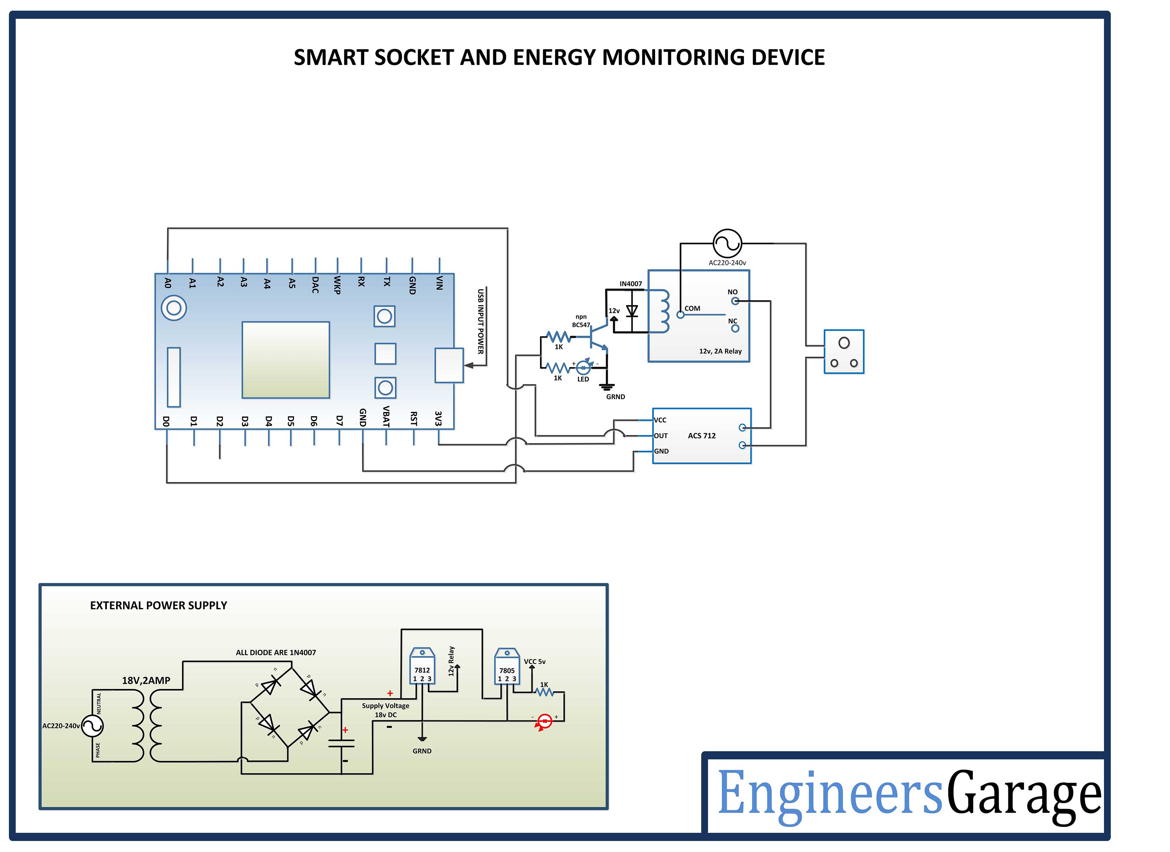 |