
Generators play an important role in our modern world, providing the electricity that powers our homes, industries and technologies. To ensure a reliable and consistent power supply, it is crucial to understand the factors that determine generator performance. At the heart of a generator's operation is the electromotive force (EMF) equation, a fundamental principle that greatly influences its efficiency and performance. Maxwell's equations, charge, permittivity, permeability, vacuum, speed of light, ampere and Tesla are the key elements that form the basis of this influential principle.
Optimizing generator efficiency
The efficiency and performance of generators are crucial factors for a reliable and constant power supply. At the heart of how they work is the electromotive force (EMF) equation, a fundamental principle that governs how they work. Engineers and enthusiasts need to understand the EMF equation and its role in generator performance. This equation provides valuable information about the production of electrical energy, the relationship between magnetic fields and currents, and the factors that affect the overall efficiency of generators. In this article, we will delve into the complicated workings of the EMF equation and examine how it affects the performance and capabilities of generators, highlighting the key elements that influence their efficiency and energy production. By understanding the meaning of the EMF equation, we can unlock the secrets behind optimizing generator designs and ensuring a continuous flow of electrical energy.
Total number of anchoring conductors = number of slots * number of conductors/slot.
P = number of poles.
A = Number of parallel paths in the anchor.
N = armature speed in rpm.
E = Electromotive force induced in each parallel path in the armature.
Electromotive force generated = electromotive force generated in one of the parallel paths.
Average electromotive force generated/conductor = (dφ/dt) volts.
Now, the flow/conductor section in one revolution is dφ = (φ*P) orbit.
Number of revolutions per second = N/60;
So the time for one stroke is dt = 60/N second.
According to Faraday's laws of electromagnetic induction, the following applies:
Electromotive force/generated conductor = (dφ/dt) = (φZPN/120) volts.
For a wave winding generator
The number of parallel paths is 2
Number of conductors (in series) in one course = Z/2
For a generator with loop winding
Number of similar titles = P
Number of conductors (in series) in one passage = Z/P
So electromotive force/distance generated = ((φPN/60)*(Z/P)) = (φZN/60) volts.
In general, the generated electromotive force (EMF) = ((φPN/60)*(Z/A))= (φZPN/60A) volts
Where A=2 for wave winding.
A = P for lap winding.
Understanding the EMF Equation: An Overview
What is the EMF equation?
The electromotive force (EMF) equation is a fundamental principle of electromagnetism that relates the voltage or electromotive force induced in a conductor to the rate of change of magnetic flux through the conductor. Simply put, it quantifies the production of electrical energy in a generator. The EMF equation provides a mathematical representation of the relationship between magnetic fields and currents and forms the basis for understanding the operation and performance of generators.
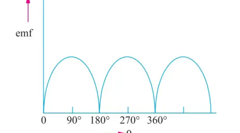
According to the EMF equation, the electromotive force (EMF) generated is directly proportional to the rate at which the magnetic flux changes over time. Mathematically, this can be expressed as follows:
EMF = -dϕ/dt
The term EMF stands for induced electromotive force. dϕ/dt denotes the rate of change of the magnetic flux. If the equation contains a negative sign, the induced electromagnetic force opposes the change in magnetic flux. The EMF equation shows that when the magnetic field changes, for example due to the rotation of a magnet or a changing current flowing through a coil, an EMF is induced in the conductor.
Components of the EMF equation
The EMF equation consists of several main components that play a critical role in determining the magnitude and characteristics of the induced electromotive force. Understanding these components is important to understanding the factors that affect generator performance. Here are the main features of the EMF equation:
Magnetic flux (ϕ)
It represents the measurement of the magnetic field lines that pass through a specific area. It is a fundamental concept of electromagnetism and is denoted by the symbol ϕ. The strength and density of the magnetic field are directly related to the magnetic flux. In the context of the EMF equation, the determination of the magnitude of the induced electromotive force strongly depends on the rate of variation of the magnetic flux, which is characterized by (dϕ/dt).
Area (A)
Area (A) is the cross-sectional area of the conductor or coil through which the magnetic flux flows. This is an important parameter that influences the entire magnetic flux chain and therefore the induced electromotive force. The larger the area, the greater the magnetic flux that flows through it, resulting in a greater induced electromotive force.
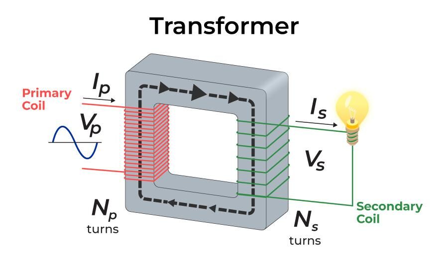
Number of revolutions (N)
The number of turns (N) is the total number of turns of wire in a coil or conductor. It influences the entire magnetic flux chain because each turn contributes to the total magnetic field intensity and induced electromotive force. Increasing the number of turns improves the binding of the magnetic flux and therefore also the induced electromotive force.
Change in magnetic flux (dϕ/dt)
The rate of change of magnetic flux (dϕ/dt) is a critical part of the EMF equation. It represents the rate at which the magnetic flux flowing through the conductor changes over time. The rate of change can be influenced by several factors, such as generator speed or coil current fluctuation – a higher rate of change of magnetic flux results in a higher induced electromotive force.
Engineers can optimize generator designs by manipulating these components to achieve specific performance goals. Factors such as conductor size and shape, number of wire turns, and flow velocity variation can be carefully adjusted to improve efficiency, voltage regulation, and overall performance of generators. The components of the EMF equation provide valuable information about how generators work and serve as a basis for designing and improving power generation systems.
Importance of EMF equation in generator design
The EMF equation is important in generators because it is a fundamental principle that governs their operation and performance. Understanding and applying the EMF equation is critical for engineers and designers in several ways:
Voltage regulation
Using the EMF equation, engineers can establish a relationship between the induced electromotive force and the rate of change of magnetic flux. This understanding is fundamental for voltage regulation in generators. By carefully manipulating components of the equation, such as magnetic field strength and speed, engineers can design generators that maintain stable voltage output even under varying load conditions. This ensures reliable operation and prevents voltage fluctuations that could damage connected electrical devices.
Efficiency optimization
The EMF equation plays a crucial role in optimizing the efficiency of generators. By considering the different components of the equation, such as: Such as the number of turns, area, and rate of change of magnetic flux, engineers can optimize generator designs to maximize energy conversion. Minimizing losses and optimizing the conversion of mechanical energy into electrical energy leads to greater overall efficiency. This is crucial to reduce fuel consumption, operating costs and environmental impact.
Power output regulation
The EMF equation provides information about the factors that affect a generator's power output. Engineers can design generators that can deliver the desired power by understanding the relationship between magnetic flux, number of turns, and rate of change of flux. This knowledge is critical to sizing and selecting generators based on specific application requirements and ensuring they can efficiently meet electrical load needs.
Project optimization
The EMF equation helps engineers optimize generator design. When designers understand the effects of several variables in the equation, such as conductor geometry, magnetic field strength, and winding configuration, they can make informed decisions to improve generator performance. These include selecting appropriate materials, improving refrigeration systems and reducing losses through advanced insulation techniques. Design optimization based on the EMF equation results in more compact, reliable and cost-effective generators.
Conclusion
In summary, the EMF equation is extremely important in generator design. It allows engineers to regulate voltage, optimize efficiency, control power production, and optimize the overall design of generators. By leveraging insights from the EMF equation, designers can design generators that meet specific requirements and ensure reliable operation, energy efficiency and optimal performance.
Common questions
What is EMF and what does the EMF formula represent in a generator?
EMF stands for Electromotive Force and represents the difference in electrical potential created by a source such as a battery or generator. The EMF formula is EMF = ε – (I * r), where ε is the electromotive force, I is the current flowing through the circuit and r is the internal resistance of the source.
How does the EMF formula help you understand battery performance?
The EMF formula is essential for evaluating the efficiency of a battery and its ability to supply electrical energy to a circuit. Knowing the EMF and internal resistance of the battery allows you to calculate the voltage drop across the terminals under different loads, thus determining the battery's performance in different situations.
Can you explain the meaning of the EMF formula in electrical circuits?
The EMF formula is essential in electrical circuits because it helps determine the potential difference that drives electrical current through the circuit. It takes into account the internal resistance of the source, which affects the total voltage delivered to the connected components. Understanding the EMF formula helps in circuit analysis and design and ensures optimal device performance.
What is the difference between the EMF formula and the potential difference (voltage) formula?
Although EMF and potential difference both refer to voltage, they are different concepts. Taking internal resistance into account, the EMF represents the total electrical potential difference that a source produces. On the other hand, the potential difference between certain components of a circuit is calculated according to Ohm's law: V = I * R, where V is the voltage, I is the current and R is the resistance of the component.
What factors can influence the electromotive force of a generator or battery?
Several factors affect the electromotive force (EMF) of a generator or battery. The most important factors include the type of cell used (e.g., lead-acid, alkaline), the material of construction, the temperature, and the chemical reactions within the cell. Additionally, the amount of charge present in the battery and the age of the battery can also affect its electromotive force (EMF).


