A DC compound generator is a direct current generator that combines the properties of a shunt generator and a series wound generator. It is often used in applications where a generator must provide constant voltage and high starting torque.

Characteristics of a separately excited generator
A separately excited generator is an electrical generator in which the field winding (the coil that creates the magnetic field) is powered by a separate, independent power source. This arrangement allows precise control of the output voltage and other performance characteristics of the generator.
External features

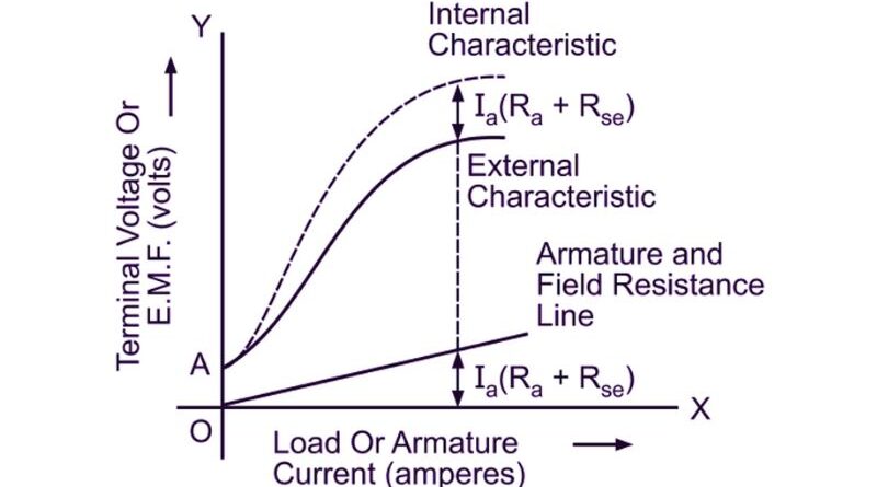
The external characteristic curve of a cumulative compound generator is shown in the figure above. Series excitation favors shunt excitation. The degree of connection is affected by increasing series excitation with increasing load current.
(i) If the turns of the series connected winding are adjusted in such a way that the terminal voltage increases with increase in load current, it is called an oversized generator. In this case, the series field mmf becomes larger due to the increase in load current and tends to increase the flux and therefore the generated voltage. The increase in generated voltage is greater than the drop in IaRa, so the terminal voltage does not decrease, but increases, as shown in curve 1 in Fig.
(ii) If the series windings are adjusted in such a way that the terminal voltage remains constant as the load current increases, it is called a flat compound winding generator. The series winding of such a machine has fewer turns than the overconnected device and therefore does not increase the maximum amount of variable load current. Thus, the voltage at full load corresponds to the voltage at no load, as shown in curve 2 of Fig.
(iii) If a series field coil has fewer turns than a flat compound generator, the source voltage decreases with increasing load current, as shown in Curve 3 Fig. Such a machine is called a subcompound generator.
Internal features
On the other hand, the internal characteristics of a generator describe the relationship between the electromotive force (EMF) generated and the field current (If) supplied to the field winding. This diagram shows how the emf produced by the armature varies with changes in field current while the load current remains constant.
The internal characteristic of a separately excited generator is generally a straight line. This means that the electromotive force generated is directly proportional to the field current. As the field current increases, the induced electromotive force also increases linearly. The slope of the internal characteristic represents the voltage regulation capacity of the generator. A steeper slope indicates better voltage regulation, while a flatter slope indicates weaker voltage regulation.
Requirement for maximum efficiency of a direct current machine
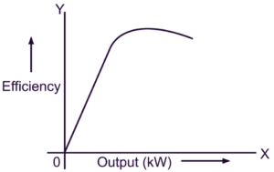
To achieve maximum efficiency from a DC machine, several conditions must be taken into consideration. Here are the key factors that help maximize the efficiency of a DC machine:
Copper losses
Losses in copper arise from the resistance of the armature and field windings. To achieve maximum efficiency, copper losses must be minimized. This can be achieved by using low resistance copper conductors for the windings and ensuring adequate cooling to avoid excessive temperature rise which increases resistance and therefore copper losses.
Iron losses
Iron losses, also known as core losses, arise from magnetic hysteresis and eddy currents in the machine core. To minimize iron losses, high-quality magnetic materials with low hysteresis and low eddy current losses must be used. Additionally, optimizing magnetic circuit design, such as using laminated cores to reduce eddy currents, can help reduce iron losses.
Brush and contact losses
Slip rings, commutators, or slip rings in a DC machine cause additional brush and contact losses. To minimize these losses, high quality brushes must be used, with good electrical conductivity and low friction properties. Proper brush alignment and regular maintenance, such as cleaning and lubrication, are also essential to reduce brush and contact loss.
Air resistance and friction losses
Wind losses arise from the resistance that the moving parts of the machine offer to the surrounding air. Friction losses arise from mechanical friction between different components. To minimize these losses, efficient bearings must be used and mechanical friction must be reduced through adequate lubrication. Rationalizing machine design and optimizing ventilation can also help reduce wind losses.
Magnetic saturation
Magnetic saturation occurs when the intensity of the magnetic field reaches its maximum value and can no longer increase in proportion to the increase in current. Operating the machine close to the magnetic saturation point reduces its efficiency. To avoid saturation, the device must be designed to operate within the rated current and voltage limits. Furthermore, controlling the excitation current to ensure it remains within the optimal range is essential to avoid magnetic saturation.