by Sebastiano Grasso, Leonardo Agatino Miccoli, Giusy Gambino, Filippo Scrimizzi, STMicroelectronics, Catania, Italy
The automotive landscape is constantly evolving, driven by growing demand for automation, safety improvements and energy efficiency. Within this dynamic environment, the implementation of DC motors in automotive body applications has gained significant prominence. These versatile engines find application in both traditional combustion vehicles and modern electric vehicles, serving diverse functions such as door locking, window control, pump operation, steering adjustments and trunk power. Employing dedicated silicon motor drivers to control DC motors offers many advantages, including increased reliability, ease of use, comprehensive monitoring and protection capabilities, and the ability to implement advanced drive features.
A notable way to introduce advanced and luxurious features is to utilize PWM (pulse width modulation) input signals to drive motors. Adjusting the duty cycle of the PWM signal allows precise modulation of motor speed and torque. However, the use of PWM signals can introduce substantial electromagnetic interference (EMI), potentially leading to complications such as radio frequency interference and signal distortion. In severe cases, EMI can pose serious safety risks by interfering with critical vehicle systems such as airbags, anti-lock brakes, and electronic stability control. Therefore, it becomes imperative to meticulously design and operate the engine and its control circuits to minimize EMI and ensure reliable operation of all electronic systems in the vehicle. This objective can be achieved through prudent component selection, grounding and sound shielding techniques, and effective filtering mechanisms that reduce switching noise and other sources of EMI.
Steering column motor control
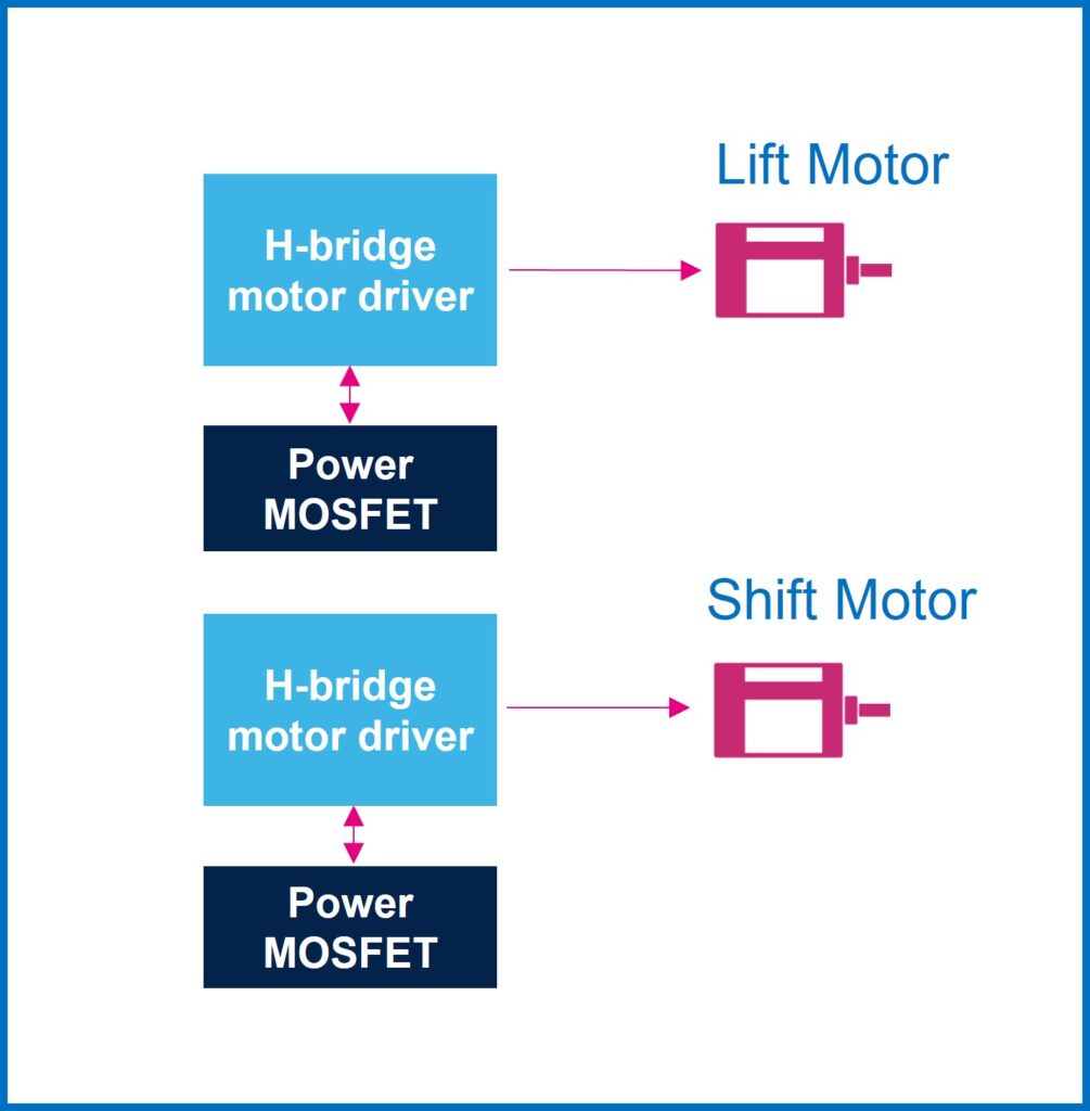
Automakers are increasingly turning to brushed DC motors for vehicle steering column applications to enhance the driving experience, improve driver comfort and reinforce safety measures. Inside the steering column, lift and shift motors are commonly used to adjust the height and position of the steering wheel. The lift motor makes it easy to raise or lower the steering column to accommodate drivers of various heights, while the shift motor allows the steering wheel to move back and forth to ensure a comfortable driving position. Figure 1 illustrates a typical block diagram for this application.

Figure 1. Block diagram of the steering column with two motors.
The typical architecture for driving a bidirectional DC motor is the H-bridge configuration. The ST VIPower M0-7 VNH7 family features several DC motor drivers specially adapted for automotive applications. Combining logic functions and power structures in a single package, these VIPower M0-7 H-bridges offer drive, protection, fault management, and advanced diagnostic capabilities while minimizing floor space. Among these, the VNHD7008AY and VNHD7012AY models are excellent options for controlling steering column actuators. Housed in the PowerSSO-36 package, they ensure direct integration into new or existing projects. The VNHD7008AY/VNHD7012AY requires two external power MOSFETs to complete driver functionality. STMicroelectronics' high-performance products, STL76DN4LF7AG and STL64DN4F7AG, are designed based on STripFET F7 technology and are AEC Q101 qualified, making them ideal for automotive applications. The dual-island PowerFLAT 5x6 package is another noteworthy feature, conserving precious PCB space.
The VNHD7008AY / VNHD7012AY allows dual motor operation in clockwise and counterclockwise modes, with a frequency of 20 kHz and a pulsed power supply with an 85% duty cycle.
EMI Test
For measuring EMI within a specific frequency range, a specialized setup is deployed that employs a rod monopole antenna in accordance with the international standard CISPR 25. These measurements are performed in an anechoic chamber to minimize external interference, as illustrated in Figure 2 .
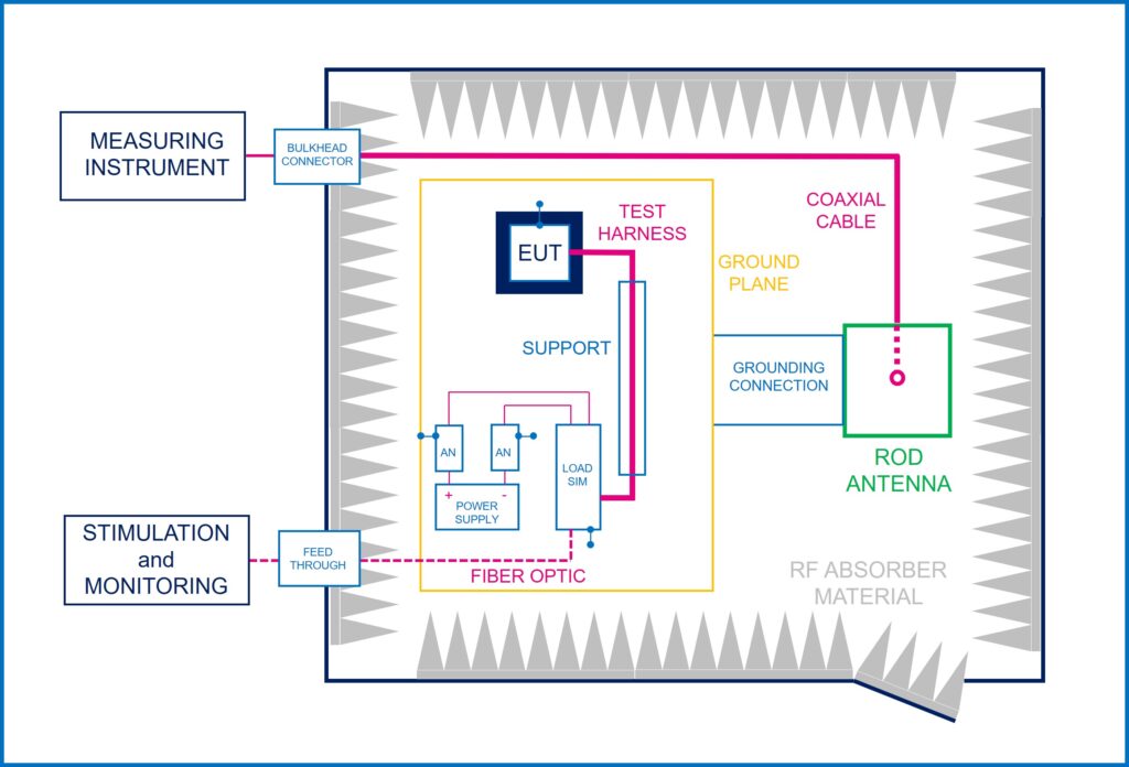
Fig. 2 Block diagram of the EMI test setup.
This configuration is composed of several components, including the equipment under test (EUT), which is grounded locally according to the test plan, a load simulator (Load sim), an artificial network (AN) and a support structure with low relative permittivity. (εr ≤ 1.4). The rod antenna used in the setup typically measures 600mm by 600mm, ensuring accurate and reliable EMI measurements via an emission test receiver positioned outside the chamber. The receiver parameters are aligned with the CISPR 25 standard, as detailed in Table 1.

Tab. 1 Test receiver emission parameters (CISPR 25 standard).
The table provided above (Table 1) displays different types of transmissions, which are defined as follows:
- LW: long wave
- MW: medium wave
- SW: Short wave
- FM: Frequency Modulation
- TV band: TV band
- DAB: digital audio broadcast
- DTT: digital terrestrial television
- SDARS: Satellite Digital Audio Radio Service.
Guidelines for EMI Mitigation
The experimental results inform us about guidelines for optimizing EMI in a steering column application employing the VNHD7008AY or VNHD7012AY DC motor driver.
- Initial condition
The steering column does not have a ground on the original application plate and there is no compensation network installed. Emissions are recorded using peak and average detectors as shown in Figure 3.
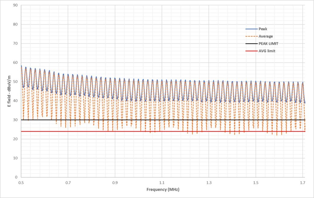
Fig. 3 Emission waveforms measured with the original plate.
The AM band (amplitude modulation), covering LW, MW and SW, presents high levels of emission. Notably, emissions in the frequency range of 0.5 MHz to 1.7 MHz exceed specified limits.
- Earth connection
An effective guideline, validated through experimentation, involves directly grounding the steering column body. The emission profiles for mean and peak values after this modification are shown in Fig.
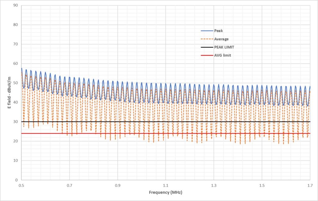
Fig. 4 Emission waveforms measured with ground connection.
Analysis reveals that grounding the steering column body improves EMC (electromagnetic compatibility) performance. However, it is important to note that these emissions primarily result from the harmonics of the PWM (pulse width modulation) signal and the sharp, asymmetrical edges of the rising and falling waveforms. Managing input noise becomes a challenge due to the high current flow in the battery line, requiring high saturation current inducing filters that can impact the overall cost of the application.
- Slowing the Edges of Change
To minimize emissions in the 0.5 MHz to 1.7 MHz range, it is recommended to reduce the speed of the switching edges and optimize the balance between the rising and falling edges. Various actions can be taken, as illustrated in Fig.
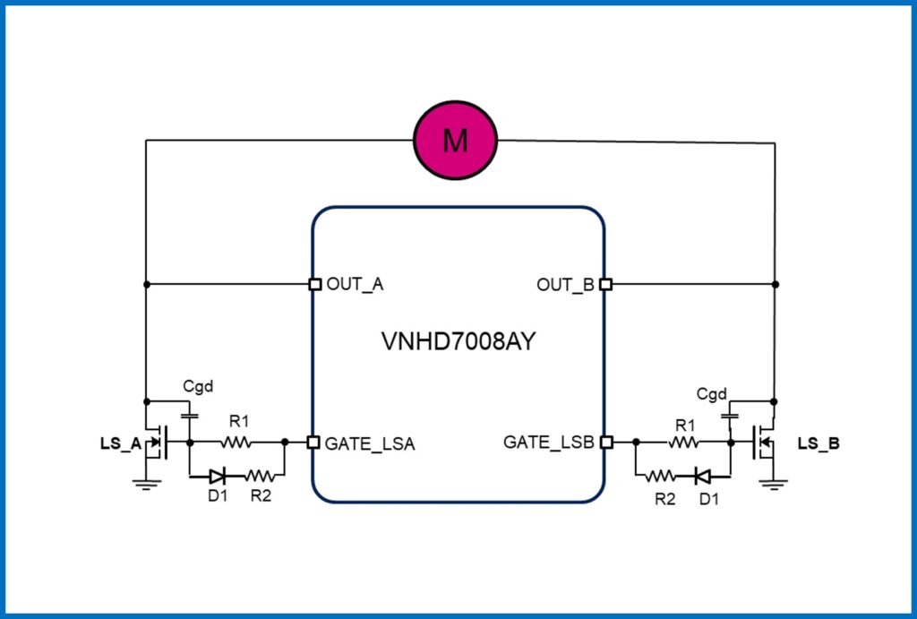
Fig. 5 Block diagram with circuit optimization.
Incorporating an additional gate drain capacitor increases the total gate drain capacitance, effectively slowing down the switching phase of the LS power MOSFETs. Increasing the gate resistance of the MOSFETs and introducing an asymmetric gate drive circuit balances the up and down switching waveforms. Modifying the input filter capacitance value further helps reduce emissions within this frequency range.
3.1 Extra gate drain capacitor
Adding an extra gate drain capacitor to the LS external power MOSFETs results in an average emissions reduction of approximately 10 dBµV/m over the 0.5 MHz to 0.8 MHz frequency range and approximately 20 dBµV/m between 0.8 MHz and 1.7 MHz. This improvement remains consistent regardless of whether the steering column body is grounded, although grounding can further reduce electromagnetic interference and improve overall system performance. A maximum value of 470 pF is recommended for the extra gate drain capacitor to avoid abrupt system shutdown. Excessive increase in the increasing switching slope may trigger the VDS (drain source voltage) protection built into the VNHD7008AY/VNHD7012 (specifically designed to protect the motor against short circuits in the battery line). Although higher capacitance values (up to 560 pF) may be acceptable, they are not recommended due to variations in capacitance values and temperature range tolerance. A value of 470 pF guarantees a safe margin, taking these factors into account. Figure 6 shows the best results obtained with this circuit modification, incorporating the extra drain capacitor and a grounded steering column.
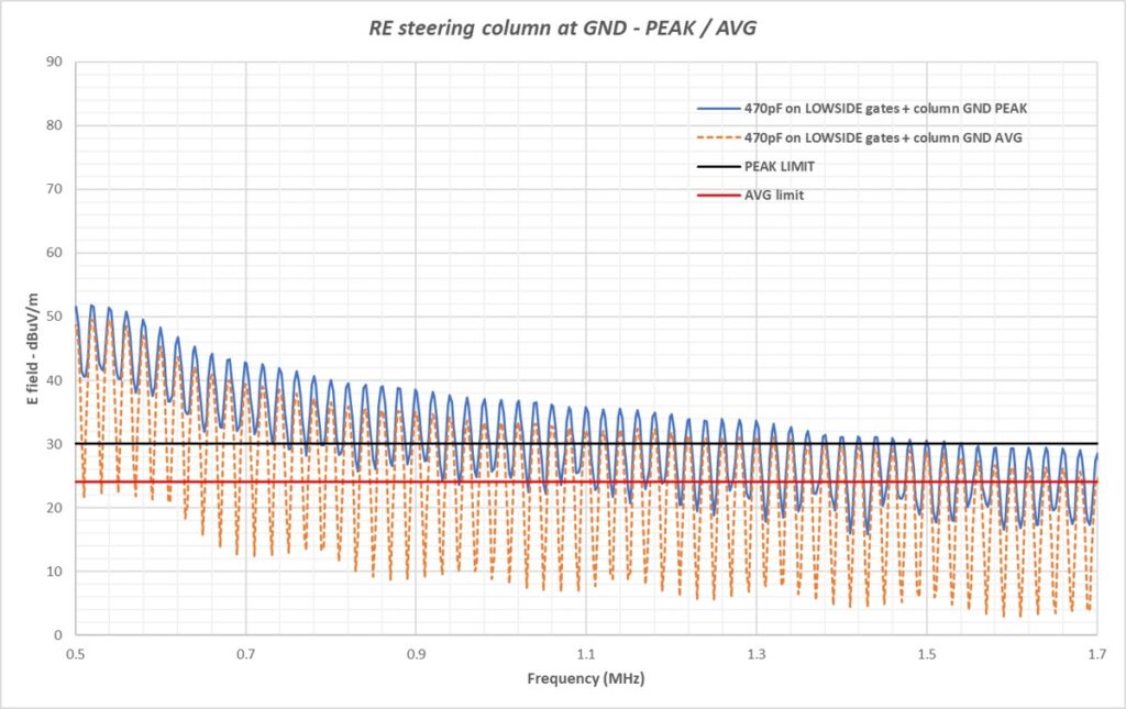
Fig. 6 Emission waveforms measured with ground connection
and extra gate drain capacitor.
3.2 Asymmetric gate drive
This circuit optimization involves increasing the resistance from the output of the DC motor drivers to the gate of the LS MOSFETs, as indicated in Fig.
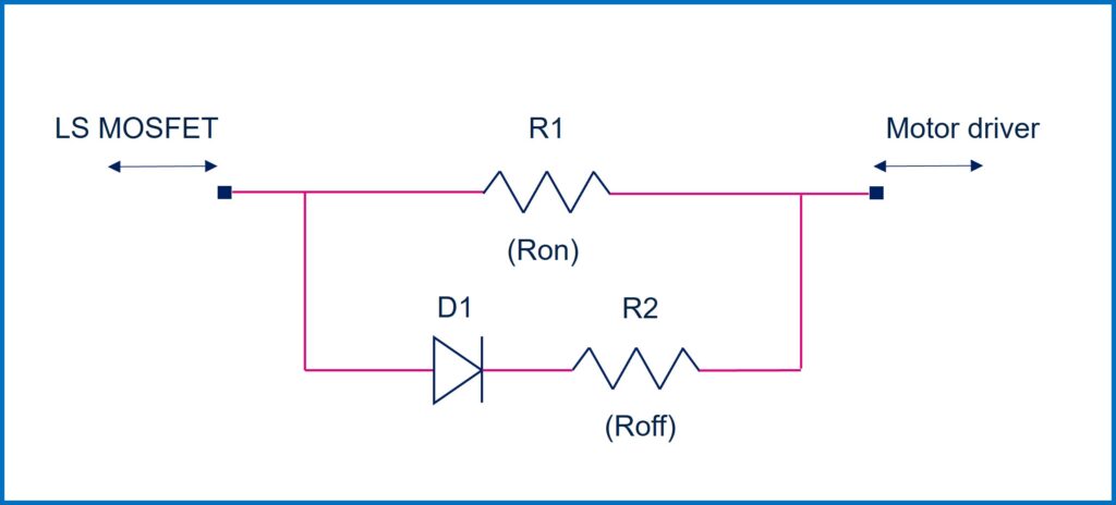
Fig. 7 Proposed circuit for asymmetric gate activation.
To reduce electromagnetic emissions, two solutions can be implemented. The first solution involves increasing the gate resistance (R1) from 470 Ω to 1 kΩ. The second solution involves introducing a diode (D1) with a resistance (R2) set at 470 Ω to obtain asymmetric gate activation. Additionally, increasing the gate drain capacitance can result in more balanced switching waveforms, with smoother rising and falling edges at the motor terminals. Figure 8 demonstrates the effectiveness of these solutions in reducing emissions, assuming a grounded steering column body.
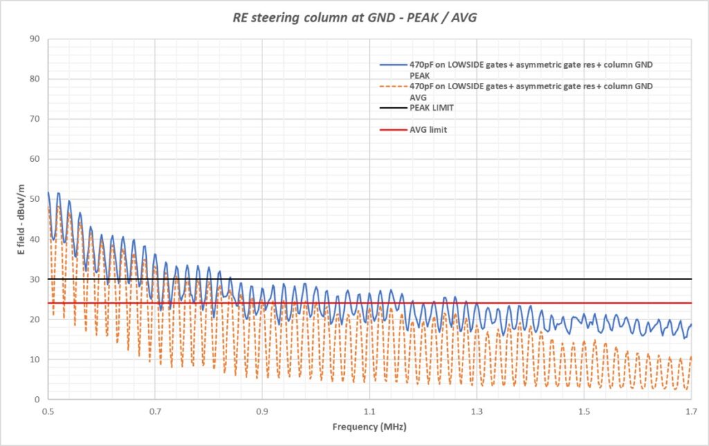
Fig. 8 Emission waveforms measured with ground connection
and asymmetrical gate activation.
This proposed solution maintains emission levels below the normative limits of CISPR 25 within the frequency range of 0.9 MHz to 1.7 MHz. To clarify the effect of the asymmetric gate driver, it is worth considering some test measurements carried out on an application board loaded with a simulated resistive-inductive (RL) load including a 2 Ω resistor with a 13 µH inductor. With a 470 Ohm gate resistor mounted on the LS MOSFET gates, falling switching edges are significantly faster (about 170 ns) than rising edges (about 800 ns). Introducing the asymmetric gate driver with specified values results in more balanced falling and rising switching waveforms. Figure 9 provides a visual representation of these waveforms.

Fig. 9 Switching waveforms measured with asymmetric gate drive.
In summary, the combination of balanced rise and fall switching times and controlled switching speed leads to an overall reduction in emission levels, particularly in the frequency range associated with EMI.
3.3 Extra Filtering Capacitance
It is advisable to include an extra capacitor in the input filter equipped with a 1 µH inductor to further reduce emissions, especially in the lower frequency range. The cumulative impact of all suggested modifications is demonstrated in Fig. 10, showing the measured peak and average spectra.
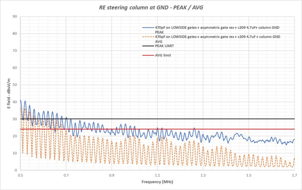
Fig. 10 Measured emission waveforms with all suggested circuit modifications.
Although a lower frequency range may still exhibit emissions that exceed standard limits, this can be addressed by implementing an additional input filter, offering potential performance improvements ranging from a minimum of 10 dBµV/m to a maximum of 30 dBµV /m. However, this may have cost implications for the overall implementation.
Conclusions
A comparative analysis of the emission spectrum in the initial scenario (blue line) and the proposed solution (yellow line) is presented in Fig. 11, summarizing the overall improvements achieved.
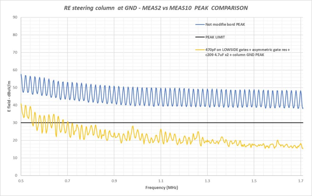
Fig. 11 A comparison of measured emissions between the initial case and all suggested solutions.
Recommended application modifications effectively reduce the emission rate of a DC motor control system, ensuring compliance with the specification limits of the CISPR-25 standard within the 0.5 MHz – 1.7 MHz frequency range. Table 2 summarizes the average reduction in peak emissions achieved through sequential implementation of different solutions.
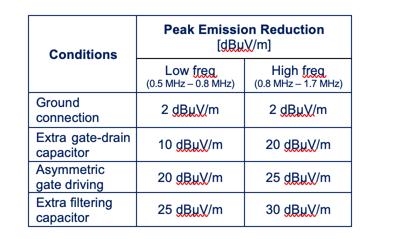
Table 2 Average reductions in peak emissions.
The results highlight the effectiveness of the proposed modifications in reducing emission rates in a DC motor control system application and ensuring compliance with the specification limits of the CISPR-25 standard. This is essential for the reliable and safe operation of the system.