ESP8266 and ESP32 are popular WiFi development solutions that can be programmed in a variety of ways using different programming languages. Common languages include MicroPython scripting, C, JavaScript, and LUA. The choice of embedded firmware and software tools makes it possible to program ESP8266 and ESP32 in different languages.
The versatility and flexibility to program ESP boards with different firmware, programming languages, and software tools make these boards so popular. The variety of firmware and programming languages also facilitates different levels of software features, community support, modules, and tools.
Embedded software developers with different programming experiences can choose their preferred firmware and programming language to develop IoT projects with ESP8266. (Learn more about programming ESP boards here ).
A common way to program ESP8266 and ESP32 is to use embedded C via Arduino IDE or Visual Studio Code. An advantage of being Arduino compatible means that there are many ready-to-use libraries and community-contributed source codes for reuse on ESP boards. It is also fast because it is unnecessary to write code from scratch to interface most components, and many programming tasks are readily solved.
Let's start programming ESP boards via Arduino IDE.
ESP8266 versus ESP32
ESP8266 and ESP32 are development boards from the same family. ESP32 is the successor of ESP8266 and superior to ESP8266 in many aspects. However, both boards have a 32-bit controller and operate at an operating voltage of 3.3V (compared to 5V for the Arduino). Both also lack hardware PWM.
Here are the differences:
ESP8266 has…
- A single-core 32-bit Xtensa L106 running at 80 MHz clock
- WiFi only
- One 20 MHz channel for WiFi (HT20)
- Two SPI ports, 1 I2C port, 2I2S and 2 UART ports
- 17GPIO
- A single 10-bit ADC
- Eight software PWM channels
ESP32 has…
- A 32-bit dual-core Xtensa LX6 running at 160~240 MHz
- High-speed WiFi and Bluetooth, including 4.2 and Low Energy
- One 40 MHz channel for WiFi (HT40)
- Touch-sensitive pins and a built-in Hall sensor wake you from a deep sleep
- 512 bytes of flash memory and 512 KB of SRAM
- CAN 2.0 interface, Ethernet MAC interface and touch sensor and Hall effect
- 34GPIO
- GPIOs are multiplexed with SPI, I2C and UART (if a function is not defined in the code, the pins default to GPIO).
- 18 analog-enabled pins with a 12-bit ADC channel on each pin
- 16 software PWM channels
Despite the differences between the two boards, the Arduino IDE works almost identically to either one. Since the ESP8266 is older than the ESP32, it has greater library support, although it is not difficult to get most libraries to work with the ESP32. It is more powerful and versatile.
ESP8266 versions
ESP8266 and ESP32 can be independent modules or breakout boards with additional chips and interfaces. Typically they are used as breakout boards for designing embedded applications and rarely as simple chips.
Many ESP8266 breakout boards fall into two categories: development boards with a USB interface or without a USB interface. Several independent modules are available in the ESP-NN series (ESP01 to ESP14) from the supplier AI-Thinkers. Another independent module is the ESP-WROOM-02 from Espressif. Other providers include Wireless-tag, Olimex, Smarttime and Qilianer.
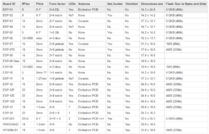
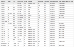
A comparison of available standalone ESP8266 modules.
The stand-alone modules serve as Wi-Fi adapters or Wi-Fi-enabled microcontroller development boards. Modules vary in size, broken pins, exposed features on the chip, antenna type, and flash memory.
A basic ESP8266 SoC requires an external flash memory, reset and program circuitry, chip enable circuitry, a 3.3 voltage regulator power supply, and a USB to serial adapter. The required resources can be integrated into a module or provided externally.
ESP8266 based development boards are equipped with all necessary circuitry with or without USB interface for programming. Some popular ESP8266 development boards are available from Adafruit, SparkFun, NodeMCU, and AI Thinkers.
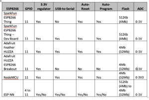
Features of some of the available ESP8266 development boards.
The ESP8266 categories…
1. Development boards with USB interface : it has a USB interface for programming with all the necessary circuits, not requiring an external circuit for configuration (at most, it may be necessary to solder the header pins). Examples include SparkFun ESP8266 Thing, Adafruit Feather HUZZA, SparkFun Blynk Board, and certain AI Thinker ESP-NN boards.
When these cards are connected to a desktop computer via a USB cable, they appear in the device manager of a Windows PC in the lsusb of a Linux system. They have a 3.3V regulator and can be programmed directly via the USB interface.
2. Development boards without USB interface : require a USB to serial adapter for programming and an external circuit to enable the chip and add reset and programming buttons. Some boards have an integrated 3.3V regulator, but not all.
The ESP-12E or ESP-12E NodeMCU kit is the most popular ESP8266 breakout board.
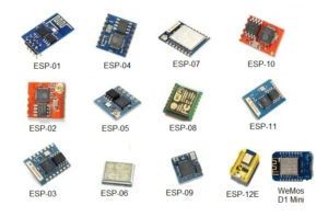
The ESP8266 modules from the ESP-NN series (ESP01 to ESP14) from AI-Thinkers.
ESP8266 pinout
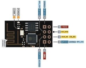
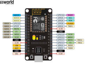
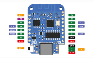
ESP-01, ESP8266-12E NodeMCU kit and Wemos D1 Mini are commonly used ESP8266 breakout boards.
The ESP-01 has the following pin diagram…
The ESP8266-12E NodeMCU kit has this pin diagram…
Wemos D1 Mini has the following pin diagram…
ESP32 Boards
Commonly used ESP32 breakout boards include ESP32 DevKit, ESP32 DOIT DEVKIT V1, ESP32 Thing, HUZZAH32, ESP-32S NodeMCU, WEMOS OLED and WEMOS LOLIN32.
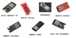
Commonly used ESP32 breakout boards.
ESP32 pinout
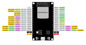
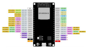
ESP32 DOIT DEVKIT V1 is currently the most popular ESP32 board. It comes in two versions, one with 30 pins and the other with 36 pins.
The 30-pin version has this pin diagram…
The 36-pin version has the following pin diagram…
Installing the Arduino IDE
Arduino IDE can be downloaded from here . Arduino IDE 2.0.0 is the latest version. The legacy version of Arduino IDE 1.8.19 can also be installed according to your preference. Complete the installation process according to the instructions.
Installing the ESP32 add-on on the Arduino IDE
ESP-32 is the most recommended ESP board to explore. ESP-32 has a powerful processor and better clock speed. It offers WiFi and Bluetooth and has more GPIOs and peripherals than the ESP8266.
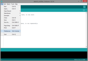
To work with ESP32 in Arduino IDE, install its add-on. Navigate to File->Preferences.
Add the following URL to the “Additional board manager URLs” field.
or
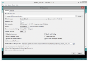
Click OK. Then navigate to Tools->Board->Board Manager.
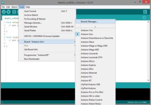
Search for ESP32 and install it on Expressif.
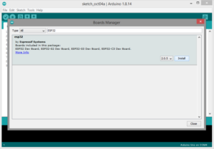
That is all. The ESP32 add-on will install on the Arduino IDE in seconds.
Installing the ESP8266 add-on on the Arduino IDE
ESP8266 is recommended for many IoT and smart home projects. Typically, the ESP8266 is sufficient if a project only requires WiFi networking and does not involve many urgent embedded tasks. Since the ESP8266 costs almost half as much as the ESP32, producing a prototype on the ESP8266 could be much more cost-effective than on the ESP32.
To install the ESP8266 add-on in the Arduino IDE, navigate to File->Preferences. Add the following URL to the “Additional board manager URLs” field.
You can add support for ESP32 and ESP8266 by adding a comma-separated list of URLs as follows…
,
or
,
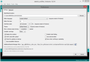
Click OK. Then navigate to Tools->Board->Board Manager. Search for ESP8266 and install it through the ESP8266 community.
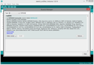
That is all. The ESP8266 add-on will be installed in a few seconds on the Arduino IDE.
Testing installation on ESP8266
To test the installation on the ESP8266, you can use the ESP-12E NodeMCU kit and connect it to the computer via a Micro-USB cable. Navigate to Tools->Board->ESP8266 Boards. Select NodeMCU 1.0 or NodeMCU 0.9 according to your ESP12 board.
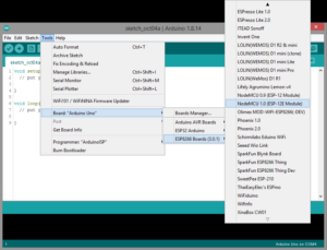
Then select the port by navigating to Tools->Port. Copy and paste the following code into the code editor…
inner pin = 2;
empty configuration {
pinMode(pin, OUTPUT);
}
empty loop {
digitalWrite(pin, HIGH);
delay(1000);
digitalWrite(pin, LOW);
delay(1000);
}
Click the “Upload” button and wait until the “Upload complete” message appears in the bottom left corner. If the code is loaded successfully, the LED on the ESP8266 board will start blinking.
Testing installation on ESP32
To test the ESP32 on the Arduino IDE, connect the board to your computer via a Micro-USB cable. Navigate to Tools-Board->ESP32 Arduino. Select DOIT ESP32 DEVKIT V1 or your specific ESP32 board.
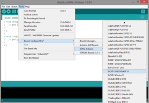
Then select the port.
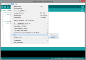
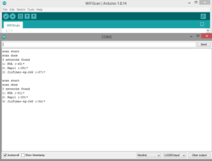
Open an example sketch by navigating to File->Examples->WiFi->WiFiScan. The sketch will open in a new window. Press the upload button and wait for the code to compile and upload.
Open the Arduino IDE Serial Monitor at a baud rate of 115,200 bps. If the sketch is loaded successfully, you will see a similar verification result in Serial Monitor.
Problems solution
When sending the sketch to ESP8266 or ESP32, you may encounter an error message like “esptool.FatalError: Failed to connect to ESP8266: Timed out waiting for packet header” or “Fatal error occurred: Failed to connect to ESP32: Timeout limit exhausted… Connecting…”.
Either message means that the ESP8266/ESP32 is not in proper flash or upload mode. To resolve this, press and hold the boot/flash button on the ESP8266/ESP32 after selecting the board and port, and then press the upload button on the Arduino IDE to upload the sketch.
After seeing the “Connecting…” message in the Arduino IDE, release the boot/flash button on the ESP8266/ESP32. After the sketch is successfully loaded into the ESP8266/ESP32, press the activate button on the ESP8266/ESP32. This will restart the ESP8266/ESP32 board and run the loaded sketch.
This must be repeated every time a new sketch is loaded into the ESP8266 or ESP32. Repeating this troubleshooting measure can be avoided on the ESP32 by hacking the board. The ESP32 can be put into flash/upload mode automatically.
To do this, you must connect a 10 uF electrolytic capacitor between the enable pin and ground. Since the enable and GND pins are far from each other on the interrupt board, the capacitor can be connected between the enable pin of the ESP32 chip and ground, as shown in the image below.
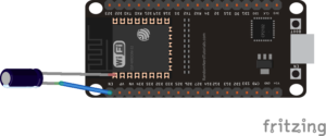
You can test the configuration on the breadboard before soldering the capacitor to the board as shown below.
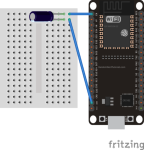
Make sure the capacitor is soldered only to the chip's enable pin and ground. It should not be soldered to anything near these pins. Once completed, you will not need to hold down the boot/flash button on the board when sending any sketches to the ESP32. ESP32 will flash and upload automatically.

