In the current technological scenario, monitoring the gases produced is very important. From household appliances, such as air conditioners, to electrical chimneys and industrial security systems, gas monitoring is very important. Gas sensors are a very important part of such systems. Small as a nose, gas sensors react spontaneously to the gas present, thus keeping the system updated on any changes that occur in the concentration of molecules in the gaseous state.
Gas sensors are available in wide specifications depending on sensitivity levels, type of gas to be detected, physical dimensions and several other factors. This Insight covers a methane gas sensor that can detect gases such as ammonia, which can be produced from methane. When a gas interacts with this sensor, it is first ionized into its constituents and then adsorbed by the sensing element. This adsorption creates a potential difference in the element that is transmitted to the processor unit through the output pins in the form of current. What is this sensing element? Is it stored in a chamber or is it exposed? How is it updated and how is it removed? Let's find out in this Insight!!!

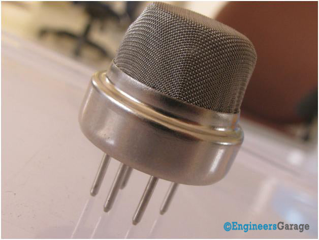
Fig. 1: Image showing a typical gas sensor
The gas sensing module consists of a steel exoskeleton under which a sensing element is housed. This sensing element is subjected to current via connecting wires. This current is known as heating current through it, gases approaching the sensing element are ionized and absorbed by the sensing element. This changes the resistance of the sensing element, which changes the value of the current leaving it.
 Figure 2: Image showing various parts of a gas sensor
Image 01 shows the external part of a standard gas sensor module: steel mesh, copper fixing ring and connection cables. The upper part is a stainless steel mesh that takes care of the following:
1. Filter suspended particles so that only gaseous elements can pass into the sensor.
2. Protecting the inside of the sensor.
3. Features an anti-explosion mesh that keeps the sensor module intact at high temperatures and gas pressures.
To efficiently manage the functions listed above, the steel mesh is made in two layers. The mesh is attached to the rest of the body via a copper-coated attachment ring.

Figure 3: Mash Steel Used in Gas Sensor
The sensor connection wires are thick so that the sensor can be firmly connected to the circuit and a sufficient amount of heat can be conducted internally. They are cast from copper and have tin plating on them. Four of the six wires (A, B, C, D) are for signal searching, while two (1,2) are used to provide sufficient heat to the sensing element.
The pins are placed on a Bakelite base which is a good insulator and provides a firm hold to the sensor connection cables.
Internal features

Figure 4: Inside view of the gas sensor after removing the steel wort
The top of the gas sensor is removed to view the internal parts of the sensor: sensing element and connecting wiring. The hexapod structure consists of the sensing element and six connecting legs that extend beyond the Bakelite base.

Figure 5: Image showing the hexapod structure inside a gas sensor
Image 4 shows the hollow sensing element which is made of aluminum oxide-based ceramic and has a tin oxide coating. The use of a ceramic substrate increases heating efficiency and tin oxide, being sensitive to the adsorption of the desired gas components (in this case methane and its products), is sufficient as a detection coating.
The wires responsible for heating the sensing element are connected using Nickel-Chromium, a well-known conductive alloy. The wires responsible for the output signals are connected using platinum wires that transmit small changes in the current passing through the sensing element. Platinum wires are connected to the body of the sensing element while Nickel-Chromium wires pass through its hollow structure.
Ceramic Sensing Element

Figure 6: Ceramic sensing element present inside a gas sensor
While other wires are attached to the outer body of the element, nickel-chromium wires are placed inside the spring-shaped element. Image 5 shows the coiled part of the wire that is placed inside the hollow ceramic.

Figure 7: A closer look at the ceramic element
Image 06 shows the ceramic with tin dioxide in the top coating, which has good adsorption properties. Any gas to be monitored has a specific temperature at which it ionizes. The sensor's task is to work at the desired temperature so that the gas molecules are ionized. By means of the nickel-chromium wire, the ceramic region of the sensing element is subjected to the heating current. Heat is radiated by the element in the region nearby where gases interact with it and are ionized. Once ionized, they are absorbed by tin dioxide. The adsorbed molecules change the resistance of the tin dioxide layer. This changes the current that flows through the sensing element and is transmitted through the output cables to the unit that controls the operation of the gas sensor .