In the previous tutorial we discussed interfacing RGB LEDs with Arduino . In this tutorial, you will learn how to interface the seven-segment display (SSD) when using Arduino.
When interfacing with any type of display device, Arduino and other controllers use digital output or serial communication. Driving SSDs through Arduino is as simple as putting an LED on it. The seven-segment display is made up of eight LED segments. They are used to display numbers.
In this tutorial, we will design a simple counter using an SSD that counts from 0 to 9 and rounds.
Seven-segment displays (SSDs)
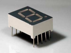
As mentioned in the introduction, an SSD is a drive made up of eight LED segments. Of these eight LED segments, seven are bar-shaped and one is a dot.
There are 10 pins in total on an SSD. Of these 10 pins, two pins are common cathode or common anode, and the rest are connected to opposite terminals of the LED segments.
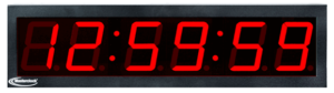
SSDs are used to display numbers. They are less expensive and often employed as an alternative to character LCDs. They are used in embedded applications where the display only needs to show numbers. Take a digital clock, for example, which displays the time in numbers. It can be built using SSDs instead of an expensive LCD.
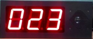
A token display board can also be built using SSDs as it only needs to display token numbers. Similarly, SSDs can be used in digital dashboards (such as those on vehicle dashboards), which display numerical information (distance traveled, fuel efficiency, etc.).
Furthermore, SSDs are used in various embedded and consumer applications where numerical data is displayed.
Some examples include:
- The display timer for a microwave or washing machine
- The temperature gauge on a heater or air conditioner
- The Value of a Coin Counting Machine
- Numbers on a calculator, etc.


Types of SSD
There are two types of SSDs:
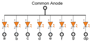
1. Common anode
2. Common cathode
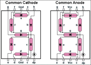
In common anode SSD, the anode of each of the LED segments has a common terminal, while the cathodes have separate terminals. To control each segment, the common anode is connected to VCC and the cathode terminals are displayed as “logical LOW” to turn the segments on and “logical HIGH” to turn them off.
In common cathode SSD, the cathodes and each of the LED segments have a common terminal, while the anodes have separate terminals. To control each segment, the common cathode is connected to ground and the anode terminals are displayed as “logic HIGH” to turn the segments on and “logic LOW” to turn them off.
How SSD works
There are eight LED segments on an SSD, of which seven are bar-shaped and one is dot-shaped. The bar-shaped LED segments are designated by the letters of the alphabet “A” to “G” and the dot-shaped LED segment is designated as “DP”.
These LED segments are organized on the SSD like this:
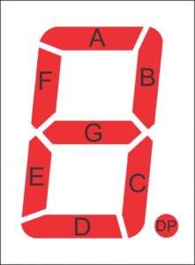
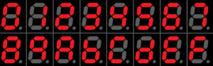
By lighting specific combinations of the LED segments, different decimal digits (0 to 9) and hexadecimal alphabets (A to F) can be displayed.
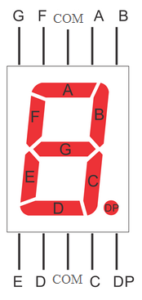
A seven-segment display has the following pin configuration:
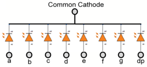
SSDs have this internal circuit diagram:
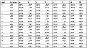
In common anode SSD, the common terminal is the anode of each of the LED segments. To display different digits and hexadecimal alphabets, the LED segments of the common anode SSD must be provided as digital logic.
This table offers a summary:
In common cathode SSD, the common terminal is the cathode with all LED segments. To display different digits and hexadecimal alphabets, the LED segments of the common cathode SSD must be provided as a digital logic.
This table offers a summary:
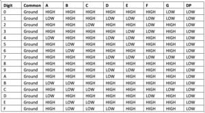
The logic table for common cathode is simply the inverse of common anode SSD. To protect the LED segments, it is advisable to connect current limiting resistors in series with each segment.
However, different LED segments may have different forward bias voltages. Therefore, resistors must be connected along each segment rather than connecting a single resistor to the common terminal. If a single resistor is connected to the common terminal, some of the LED segments may not glow because they may have a higher forward voltage. Alternatively, all segments may glow, but with different light intensity.
The resistor value must be calculated according to the segment with the highest direct voltage.
The resistor value can be calculated using this equation:
RS Series = (VS – VLED)/ILED
Where,
RSeries = Resistor value
VS = Source voltage
VLED = Highest forward voltage of LED segments
ILED = Current through LED segments
Suppose the highest forward voltage is 1.7 V, the source voltage is 5 V, and the current required through the LED segments is 5 mA to 20 mA – or consider the average of 10 mA.
Then, the value of the resistors will be:
R = (5-1.7)/10×10-3
= 330 Ohms
Driving SSD with Arduino
Interfacing the SSD with Arduino is as simple as interfacing the LEDs. The SSD can be treated as a collection of eight LEDs with a common anode or cathode.
The instructions:
- To drive the common anode SSD, the common terminal is connected to VCC and the rest of the terminals are directly interfaced with the Arduino digital I/O channels through series resistors. Channels must be set LOW to turn the LED segments ON and must be set HIGH to turn them off.
- To drive the common cathode SSD, the common terminal is connected to ground and the rest of the terminals are directly interfaced with the Arduino digital I/O channels through series resistors. In this case, the channels must be set to HIGH to turn on the LED segments, and must be set to LOW to turn them off. The Arduino's digital I/O channels produce 5V/3.3V and current sources or sinks of up to 40 mA, which is enough to drive the LED segments. By turning different combinations of LED segments on and off, different digits (0 to 9) and alphabets (A to F) can be displayed.
- To drive more than one SSD together, a multiplexing technique is used. When there are many SSDs that need to be controlled by one controller, the SSDs are interconnected through a demultiplexer or seven-segment BCD decoder IC such as SN7446AN.
Arduino based SSD driver recipe
In this recipe, we will interface a seven-segment display using Arduino UNO and display digits 0 to 9 on it.
Required components
1. Arduino UNO x1
2. SSD x1
3. 330 Ohm Resistor x7
4. Test board x1
5. Male-to-male bonding wires or connecting wires
Circuit Connections
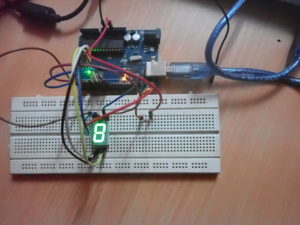
The SSD used in this project is of the common anode type. This means that the common terminal of the SSD is connected to 5V DC. SSD terminals A, B, C, D, E, F, and G are connected to digital I/O channels 4, 5, 6, 0, 1, 2, and 3, respectively.
330 Ohm resistors are connected between each channel and the respective SSD terminals. The breadboard is provided as common ground and 5V power rail from one of the Arduino UNO's ground pin and 5V pin respectively.
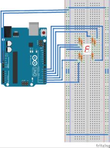
Circuit Diagram

Arduino Sketch
How the project works
To display different digits on the SSD, different combinations of LED segments are turned ON and OFF at the same time.
The SSD used in this project is of the common anode type. Thus, the common terminal of the SSD is connected to 5V DC and the other terminals are interconnected with the Arduino channels through 330 Ohm series resistors.
To display different digits, the logic table for a seven-segment common anode is applicable.
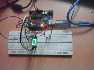
For flashing digits 0 to 9, the “0” is displayed first by turning on LED segments A, B, C, D, E and F – while LED segment G is turned off. After displaying “0” for one second, all LED segments turn off for 300 milliseconds. Note: If all segments are not turned off, the LED segments will remain lit when turned on again and successive digits will not be displayed correctly.
After displaying “0”, if all LED segments are not off, when displaying “1”, the SSD will still display “0”. It will display “8” when 2, 3, 4, 5, 6, 8 and 9 flash, then “0” when 7 flashes. Therefore, it is important to turn off all LED segments for a few milliseconds after each digit is displayed.
So, for example:
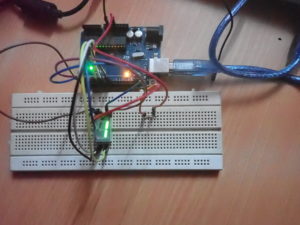
- To display “1”, LED segments B and C are turned ON while all others are OFF.
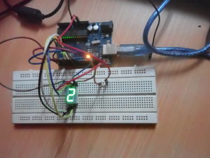
- To display “2”, LED segments A, B, G, E and D are turned ON while all others are OFF.
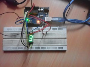
- To display “3”, LED segments A, B, G, C and D are turned ON while all others are OFF.
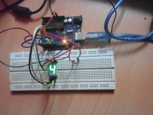
- To display “4”, LED segments F, G, B and C are turned ON while all others are OFF.
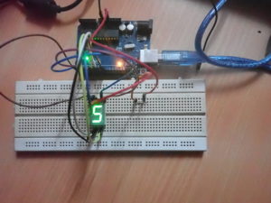
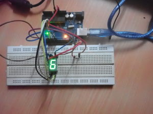
- To display “5”, LED segments A, F, G, C and D are turned ON while all others are OFF.
- To display “6”, LED segments A, F, G, E, D and C are turned on while all others are turned off.
- To display “7”, LED segments A, B and C are turned on while all others are turned off.
- To display “8”, all LED segments (except DP) are ON.
- To display “9”, LED segments A, B, F, G and C are turned ON while all others are OFF.
All LED segments turn off for 300 milliseconds after displaying a digit for one second. As the Arduino repeats its code, the display of digits 0 to 9 will continue to repeat until the Arduino is turned off.
Programming Guide
The Arduino sketch starts by defining the global variables, which correspond to the SSD terminals that are connected to the Arduino channels.
intg = 3;
int f = 2;
intuma = 4;
int b = 5;
internal c = 6;
int d = 0;
int e = 1;
In the setup function, these channels are defined as digital output using the pinMode function.
empty configuration {
pinMode(a, OUTPUT);
pinMode(b, OUTPUT);
pinMode(c, OUTPUT);
pinMode(d, OUTPUT);
pinMode(e, OUTPUT);
pinMode(f, OUTPUT);
pinMode(g, OUTPUT);
}
In the loop function, the logical digits for flash from 0 to 9 are written to the SSD. As the SSD used in this project is a common anode, when writing “logical HIGH” on a channel, the respective LED segment turns off; and when writing “logical LOW” on a channel, the respective LED segment lights up.
First, all LED segments are turned off by writing “logical HIGH” to all linked channels using the digitalWrite function. A delay of 300 milliseconds is provided after using the delay function.
empty loop {
digitalWrite(a, HIGH);
digitalWrite(b, HIGH);
digitalWrite(c, HIGH);
digitalWrite(d, HIGH);
digitalWrite(e, HIGH);
digitalWrite(f, HIGH);
digitalWrite(g, HIGH);
delay(300);
Next, the first digit “0” is displayed by connecting segments A, B, C, D, E and F of the LED, which is done by writing “logical LOW” on the respective channels.
A one-second delay is provided by calling the delay function, so that the digit “0” remains displayed on the SSD for one second.
digitalWrite(a, DOWN);
digitalWrite(b, DOWN);
digitalWrite(c, DOWN);
digitalWrite(d, DOWN);
digitalWrite(e, DOWN);
digitalWrite(f, DOWN);
delay(1000);
After displaying “0”, all LED segments are turned off for 300 milliseconds.
Then the digit “1” is displayed for one second just by turning on the B and C segments of the LED.
digitalWrite(a, HIGH);
digitalWrite(b, HIGH);
digitalWrite(c, HIGH);
digitalWrite(d, HIGH);
digitalWrite(e, HIGH);
digitalWrite(f, HIGH);
digitalWrite(g, HIGH);
delay(300);
digitalWrite(b, DOWN);
digitalWrite(c, DOWN);
delay(1000);
Similarly, the other remaining digits (from 2 to 9) are displayed for one second each by selectively turning the LED segments on and off.
After displaying each digit for one second, all segments turn off for 300 milliseconds. And, after displaying the digit “9”, the code written in the loop function continues repeating itself – flashing each digit (from 0 to 9) for one second each, for an infinite number of times.
In the next tutorial, we will discuss multiplexing SSDs.
Demo video
(tagsToTranslate)Arduino