The auxiliary gearbox output shaft is a crucial component that supports significant torque during vehicle operation. Therefore, it requires high strength.
The technical requirements of the design include the use of 40Cr material and R-angle and splined medium frequency induction hardening. The depth of the hardening layer in the R angle should be ≥ 5 mm, and the hardening layer in the groove should be 5-8 mm from the bottom of the tooth. Furthermore, the surface hardness must be ≥ 55HRC. The die should be quenched and tempered, and the hardness should be 235-265HBW.
In early 2019, the market reported that the auxiliary box output shaft frequently broke when customers drove between 30,000-100,000 km. Through analysis of the broken parts, the following reasons for fractures were identified:
- The R-angle structure of the output shaft is concave, making induction hardening difficult. This results in a shallow quench layer and greater sensitivity to crack quenching. Induction hardening cracks were found at angle R during actual detection.
- The chamfer of the oil hole of the auxiliary box output shaft is 0.5 mm × 45°. Due to the acute angle effect, temper cracks tend to be large and temper cracks are present.
Related Reading: Crack Tempering vs. Crack Forging vs. Crack Forging Crack rectification
This article provides an analysis of the causes of output shaft fractures in the auxiliary box and proposes a series of improvement measures to resolve the problem. The analysis is principle-based and the measures are designed to effectively solve the problem of output shaft fractures in the auxiliary box.
1. Failure analysis
1.1 Fault detection analysis
Figure 1 illustrates the faulty output shaft components in the auxiliary box.
Specifically, Fig. 1a shows the appearance and fracture location of the defective parts, with the red circle indicating the fracture location.
The fracture of the auxiliary box output shaft occurred at the R angle position of the tool withdrawal groove, as shown in the figure.
Furthermore, Figure 1b shows the fracture morphology, which is characterized by a straight fracture induced by the circumferential rotation of the rod.
After fracture, there are mutual wear marks at both ends, which is consistent with the characteristics of torsional fracture.
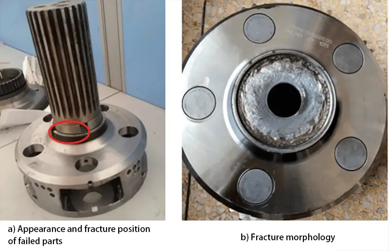
Fig. 1 Auxiliary box output shaft failure parts
Non-destructive testing and metallographic analyzes were carried out on both finished products and defective parts that were returned from the market, and the test results are presented in Table 1.
As can be seen from the table, the induction hardening results of splined parts in both finished products and market failure parts meet the technical requirements. The effective hardening depth of the splined parts is ≥ 5 mm, and the metallographic structure of the hardened layer is grade 4-5 acicular martensite.
However, the induction hardening results in the splined oil hole and R corner do not meet the technical requirements for the following reasons:
- The finished product has induction hardening cracks at the R angle position and grooved oil hole.
- The depth of the induction hardening layer at the R corner is shallow, or even non-existent, and does not exceed 5 mm as specified in the technical requirements.
Table 1 Results of magnetic particle tests and metallographic analyzes of finished parts and failed parts
| Samples | Detection location: | Metallographic examination | Non-destructive testing |
| Finished products in production | slot | DS:6~8mm,4~5 degreesM | Crack in the grooved oil hole (see Fig. 2a) |
| R Angle | Ds: 3.2 mm, 5 degree M (see Fig. 2b) | R-angle crack (see Figure 2c) | |
| Market Failure Parts | slot | Ds:7~9mm,4~5 grade M | Crack in the grooved oil hole |
| R Angle | No hardened layer (see 2d for figure) |
The above inspection results are in line with the cracking characteristics of the failed part. This is due to the fact that the induction hardening layer at the R corner of the auxiliary box output shaft is insufficiently deep and does not meet the necessary technical requirements. Additionally, an induction hardening crack developed at corner R, causing a low level of strength at that location.
During vehicle operation, the R corner is unable to withstand large torsional stresses and ultimately fractures. Additionally, induction hardening cracks are present in the splined oil hole, and several defective parts on the market have also had broken subcase output shafts at this location.
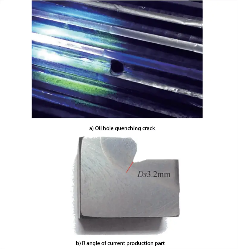
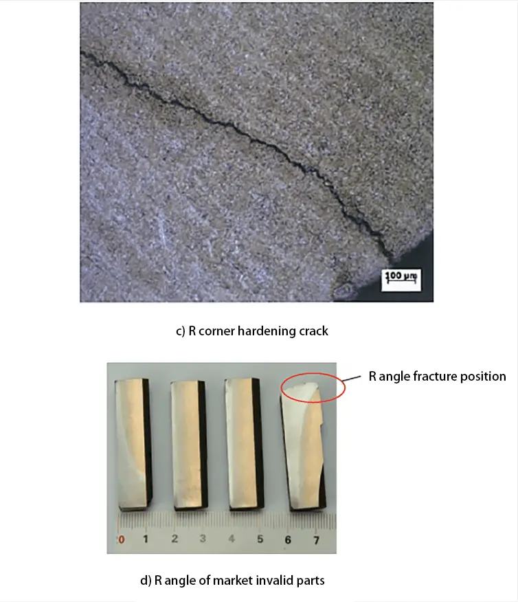
Fig. 2 NDT and metallographic test results
1.2 Analysis of the cause of failure
The fault detection results reveal two fracture risk points of the auxiliary box output shaft: the position of the R angle and the splined oil hole.
Fig. 3a illustrates the structure of the R angle position of the finished product during production. This shows that the R angle is an internal structure of R0.5 mm, which can have two effects on induction hardening.
Firstly, the transition fillet at the bottom of the R corner of the R-type internal structure is very small, causing large machining stress at the bottom of the R corner depression, which increases the sensitivity of induction hardening cracks.
Secondly, the distance between the R-angle depression of the R-type internal structure and the inductor is relatively large.
Figure 3b illustrates the distribution of induced current during induction heating at corner R.
As a result of the proximity effect of induction heating, the induced current decreases as the distance from the sensor increases. Thus, the induced current gradually reduces from areas 1 to 4, with the lowest induced current being found in area 4, located at the bottom of angle R, which is the furthest from the inductor.
In the same heating time, while areas 1 to 3 reach the required quenching heating temperature as a whole, area 4 may not reach the full quenching temperature. Consequently, water spray cooling occurs, causing martensite transformation in areas 1 to 3, but only partial martensite transformation or no transformation in area 4.
This inconsistency in the depth of the hardened layer of regions 1 to 3 and region 4 leads to uneven deformation due to structural transformation in and out of angle R. Additionally, region 4 experiences tensile stresses due to structural transformation, making it susceptible to concentration of machining stresses, ultimately resulting in the hardening of cracks during quenching.
Furthermore, since area 4 is the farthest from the inductor, it is the most challenging part for induction hardening, and the depth of the hardening layer in this area is insufficient.
Figure 3c illustrates the chamfered structure of the oil hole on the output shaft of the currently produced auxiliary tank. The design size of the oil hole is 0.5mm × 45°, which does not meet the induction hardening requirements of hole chamfers.
To ensure the quality of induction hardening, a slightly larger chamfer of more than 1 mm × 45° is required. This is because a small chamfer results in high temperatures around the oil hole due to the sharp angle effect of induction heating, leading to the formation of quenching cracks.
Furthermore, the presence of the oil hole forces the induced current to divert on both sides of the hole, resulting in unequal density of eddy currents around the hole. The eddy current density on both sides of the hole along the current direction is high, while the density on both sides perpendicular to the current direction is low. This creates a high temperature area on one side and a low temperature area on the other, as shown in Figure 3d.
Due to this uneven heating, the penetration depth of the current and the thickness of the hardened layer after quenching are different. The generation of organizational and thermal stress during induction quenching is the fundamental cause of quenching cracks at the edge of the oil hole. Furthermore, the cooling of the edge of the oil hole is more intense than that of other areas during cooling, making it more susceptible to the formation of quenching cracks.
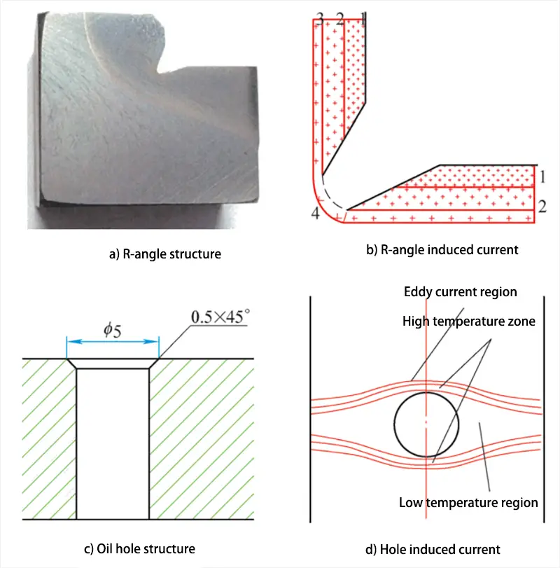
Fig. 3 R angle and oil hole
2. Improvement measures
2.1 Structural optimization of R angle and oil hole chamfer
Based on the above analysis, it is evident that the fracture of the auxiliary box output shaft is due to the defective design of the R-angle structure and the oil hole chamfer.
Consequently, the following corrective measures were developed:
- The transition fillet structure was modified to R1.5mm, and the depth of the induction hardening layer in the optimized fillet should be ≥ 3mm.
- The chamfer structure of the oil hole has been improved to (1~1.5) mm × 45°.
Figure 4a shows the optimized structure for the R angle.
During the induction heat treatment process, if the stepped root of the part requires induction hardening, a transition fillet must be incorporated. The larger the fillet, the better the result.
This design offers good processability:
① Reduces stress concentration at the root of the step and minimizes the tendency to crack during use.
② Reduces the difficulty of induction hardening, ensures uniform heating of the step root, allows a uniform and continuous hardening layer on the step, and significantly increases strength.
Figure 4b illustrates the optimized design for the oil hole chamfer, with an increased chamfer size of (1~1.5) mm × 45°. Under the same heating conditions, the larger the chamfer of the oil hole, the greater the current density at the edge of the oil hole, and the less likely it is that the edge of the oil hole will crack due to overheating.
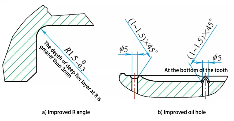
Figure 4 structural optimization
2.2 Optimization of the induction hardening process
The sweep quenching method is used to complete the quenching of the auxiliary box output shaft due to the large quenching area and small power supply. The significant advantage of sweep hardening is that it can use smaller capacity equipment to handle large parts.
To perform sweep quenching, the workpiece is placed in or near the inductor, allowing the inductor and workpiece to move relative to each other. The inductor connects high or medium frequency current to inductively heat the workpiece to the quenching temperature. Simultaneously, the inductor or water jet sprays the quenching cooling medium onto the part of the workpiece that has reached the quenching temperature.
The quenching process continues until the entire quenched area of the part has been treated. To stop the process, the inductor current is cut off first, followed by the injection of the quench cooling medium.
Figure 5 illustrates the optimized design of the inductor effective circle. This structure consists of an entire circle that rotates at a specific angle (usually 45°) to ensure adequate heating of the plane and the R angle in the variable section. The effective ring is equipped with a “Π” and the magnetic conductor groove is inclined toward the R angle area.
By taking advantage of the slit effect of the magnetic conductor, the medium-frequency current from the effective coil is expelled to the R-angle area, thereby strengthening the heating of the R-angle region. To ensure rapid heating of the R-angle, there is a gap 3-5 mm between the front end of the effective coil and the R angle. This arrangement allows the quenching temperature to be reached within 10 seconds, leading to an ideal distribution of the hardening layer.
However, when heating the R angle, the inductor must remain in this area for a specific period of time to obtain sufficient depth of the hardening layer at the R angle. During this time, the adjacent splines above the R angle will also be heated. To prevent the depth of the hardening layer of these striations from being too deep, which could result in “bulging” of the hardening layer at the transition between the R angle and the axial striation, the proximity effect of induction heating is used.
Specifically, when designing the inductor, the surface of the heating rib and the axis of the rib form an included angle of 7.5° to minimize the proximity effect. As we approach the R-angle region, the spacing decreases, leading to a black shadow in Figure 5, which indicates the distribution of induced current in the R-angle area and its adjacent regions.
Finally, when heating the corner area R, the inductor moves upward to heat and quench the splined area, resulting in a uniform, continuous hardening layer that improves the overall strength of the output shaft.
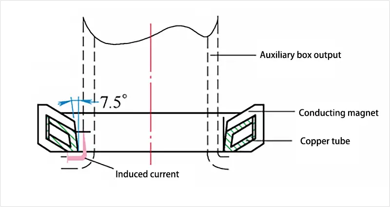
Fig. 5 Effective circle design
3. Conclusion
After analyzing the causes of the fracture of the output shaft in the auxiliary box, three improvement measures were identified:
- Transition fillet structure optimization: The transition fillet structure will be improved to r1.5mm for the outer fillet, and the technical requirement of the depth of the induction hardening layer in the fillet will be set to ≥ 3mm.
- Oil hole chamfer size optimization: The oil hole chamfer structure will be improved to (1 ~ 1.5) mm × 45°.
- Optimization of the effective structure of the inductor ring: The sweep induction hardening method will be adopted to make the hardening layer of the fillet and spline continuous and uniform.
After implementing these measures, the auxiliary box output shaft was inspected and monitored, and significant improvements were observed:
- The R-angle strength of the subtank output shaft has been significantly improved, and there are no longer induction hardening cracks in the oil hole chamfer and R-angle area.
- The output shaft fillet and hardening layer are now continuous and uniform. The hardening layer at the R angle is 4~6mm deep, while the hardening layer at the grooved part is 5~8mm deep. The metallographic structure of the hardening layer is grade 4~6 acicular martensite, and the surface hardness is 56~59HRC, meeting the technical requirements.
- The subbox output shaft did not break after delivery and loading, significantly reducing the risk of market complaints and improving product quality and customer satisfaction.