When clamping large and thin-walled bushing parts, deformation can easily occur, affecting the precision of the parts.
1. Problems
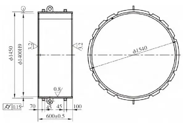
Large, thin-walled parts are easily deformed and are not only difficult to machine, but can also deform if the fixture is installed incorrectly. The accuracy is also very high. Figure 1 only shows the surface of the cylinder as an example. The hole of the part is approximately 1400 mm, the outer circle is approximately 1450 mm, and the height of the part is 600 mm. The outer circle consists of two tires at the top and bottom, the thickness is 45mm and the width is 45mm. Parts with an internal hole must be machined on a vertical CNC CK5235 × 20/32 lathe. After releasing the fixture, the part is lifted to the assembly location to ensure the required precision.
First, we used the clamping method where the clamps were pressed into the part. After processing, the clamps were released and placed on the platform. The part was checked with an inside micrometer. The result of the test was that the dimensional accuracy of the part was well outside of tolerance.
To analyze the reason for the overprecision, the clamping method was tested. The testing method is as follows: After the processing of the part is completed, while the clamping accuracy of the part remains unchanged, it is found that the roundness at any 4 or 8 points is the same. The corresponding points are divided into upper, middle and lower 3 locations to measure with the inside micrometer, mark the measuring points and record the measured value. The workpiece is aligned according to the measurement point marking and the position of the marking is measured. After a certain time, the part is aligned and registered according to the measurement point marking. The workpiece is then released, measured and recorded again according to the clinical test point marking. After several tests, it was found that the maximum single-point deformation of this method of fixing the part was 0.23–0.33 mm.

Figure.1 Cylinder body
2. Analysis of principles and improvement measures
According to the stress formula σ=F/A=Eε, ε=△l/l; σ=F/A=Eε, ε=△l/l; ε = △ l/l; ε = △ l/l; ε = △ I/I.
△l is the deformation in the direction of the force. From the above formula the following can be derived: △Eε=E-△l/l=F/A, △l=(F/A).(l/E); △l=(F/A).(l/E); △l=(F/A).(l/E); △l=(F/A).(l/E); △l=(F/A).(l/E).
Reduce the value of △l, i.e. H. reduce the deformation of the workpiece.
There are suitable solutions to effectively control and reduce the deformation caused by clamping the part during the machining process.
1) Reduce the applied force. In other cases the situation is the same, F is reduced, △l is smaller, that is, the deformation generated by the part is smaller. The measures are as follows:
- (1) Since it is not easy to accurately control the applied force, in order to facilitate the control of the magnitude of the force, the clamping force is converted into a visualized method for controlling the magnitude of the applied force F by displaying a percentage display in the direction of the applied force to see the magnitude of the deformation caused by the clamping. The percentage reading is used to determine whether the applied force meets the requirements. Please note that the applied force should not be too low, otherwise the workpiece will be thrown out, causing danger.
- (2) A torque wrench can be used to test the magnitude of the applied force. By controlling the torque wrench, experiments can be carried out to determine the clamping to achieve clamping deformation within 0.02 mm of the torque wrench value. Depending on the value of this torque wrench, attaching other parts can save time.
- (3) Apply force in the opposite direction to reduce the force at the force point. As shown in Fig. 2, by increasing the reverse force F 2 the effect of the total force F on the part is reduced.
- (4) Using a tire like B. the cylinder clamping tool in Figure 3 (can be applied to large, thin-walled internal holes and machining external curves).
The fixing holes in the screw depend on the screw diameter, the fixturing and the direct impact on the workpiece, with the maximum single point force being fixed in a relatively narrow range. The larger the screw diameter, the greater the force. Therefore, increasing the number of clamping points reduces the diameter of the clamping screw to reduce the F. End point and ensure that the total value of the clamping force F meets the requirements to ensure that the part does not move during the rotation process to achieve the objective of reducing deformation.

Figure 2 Force analysis diagram

Fig.3 Cylinder fixation
2) Increase the contact area S or the cross-sectional area of the part to reduce the pressure generated by the contact on the part and the deformation of the entire part. The measures are as follows:
- (1) Precision lathe with workpiece clamping surface, vertical lathe with self-rotating table, horizontal lathe with self-rotating disc, to ensure good contact of the workpiece clamping surface, increase the contact area of the contact surface and reduce deformation of the workpiece.
- (2) Increase the contact area of the clamping pads (or elevators). Try using a flat jack or increasing the width of the clamping pads to increase the contact area and reduce part deformation.
- (3) Through the use of flanged tires and other tools, the overall pressure of the tool on the workpiece ring is adjusted to ensure that the entire tool ring and the workpiece contact the ring track, which can significantly increase the contact area with the workpiece. And the clamping method is changed to a clamping ring to ensure that the deformation of the part is further reduced.
- (4) During construction, it is possible to thicken the parts or increase the cross-section of the part by fixing the parts to the structure. Local thickening of the part's cross-section reduces internal stresses in the part, ensuring the machining precision of parts.
- (5) Reduce the applied moment l. When clamping, place the parts as close as possible to the root of the clamping ring to not only increase the clamping contact area, but also reduce the moment applied to clamping and machining, thereby reducing the deformation of the parts.
- (6) Because in commonly used processing materials (ferrous metals, etc.), pull and ground and pressure therefore, if possible, use the entire pressure of the workpiece to clamp it, that is, the proverbial “column jack ”. This clamping method can significantly reduce the effects of clamping deformation on the workpiece.
- (7) The workpiece can be clamped with the jaws and pressure plate at the same time. That is, when applying a reverse deformation force, the total amount of deformation on the way to clamping is controlled, F connected F Pressure at the same time on the workpiece, due to the deformation of the two opposing clamping methods, so △l in the total = │△l connected – △l Pressure │. By two types of deformation displacement, △l can be made into the total reduction, but △l connected and △l Pressure There is no multiplier relationship, that is, no deformation can be greater than or equal to twice the deformation of another deformation. Otherwise, it is best to use some kind of forced fixation method.