Main Technical Index of Laser Cutter Driving Method
stroke
The stroke of a laser cutter is the processing range it can perform, which determines the maximum part size that can be processed and is a fundamental parameter.
The most common processing range currently is 3m x 1.5m, which offers a good balance between mechanical capabilities, processing range and manufacturing costs.
However, as the global industrial level continues to improve, the proportion of larger models has increased year by year.
Positioning Accuracy
As specialized machine tools, laser cutting machines are similar to traditional cold machine tools. The general transmission framework is essentially the same. However, laser cutting is typically not used for precision machining purposes, so the absolute transmission accuracy is slightly lower than that of cold NC machine tools.
The positioning accuracy of the machine reflects the manufacturer's positioning, product input and the degree of accuracy of the selected transmission parts. However, for laser cutting, positioning accuracy does not have a significant effect on the final processing result such as part size tolerances and quality of the cut section.
For fine cuts, however, laser cutting equipment can accurately cut within a dozen microns of the slit, which is on the same level as the operating precision of the laser cutter. At this point, positioning accuracy becomes very important.
Repositioning accuracy
The repositioning accuracy achieved by a laser cutting machine largely depends on the reverse backlash of the drive chain, which is similar to traditional cold machining.
The reverse clearance of the laser cutting machine also has some influence on the roughness of the cut section. Users who are very demanding on the quality of cutting sections should pay close attention to this indicator.
Positioning speed
Positioning speed, which is the most visually apparent technical parameter, is a key index that every laser cutter manufacturer pays attention to. It is often used as the main criterion for classifying mechanical properties and classes of laser cutters.
At present, top models have successively broken the single-axis positioning speed of 100m/min. High positioning speed has a significant impact on improving sheet processing efficiency.
However, for medium thickness sheets, due to cutting speed limitations, reducing the total processing time may not be as crucial.
Driving force
Due to the high flexibility of laser processing, high-speed cutting of complex parts has become the main method for various manufacturers to exhibit mechanical properties.
High speed cutting requires high torque output to the motor. The transmission chain requires high efficiency and fast response to ensure tracking accuracy and meet suppression requirements. Therefore, acceleration is as critical as positioning speed.
However, there is a trade-off between high speed and high acceleration. This requires cutter manufacturers to carefully balance the relationship and find the optimal solution through calculation and experimentation.
Transmission rigidity
During the high-speed process of a laser cutting machine, the internal tension of the drive chain may fluctuate violently. If the rigidity of the transmission is insufficient, it can easily cause track distortion and slow response of the final output. This makes the accuracy of dynamic operation far from low or static measurement values, which may affect the dimensional accuracy and roughness of the workpiece.
However, this index is not easily quantified.
4 laser cutting machine driving methods
Synchronous belt drive
The timing synchronous belt (shown in FIG. 1) is mainly composed of pulleys and belts.
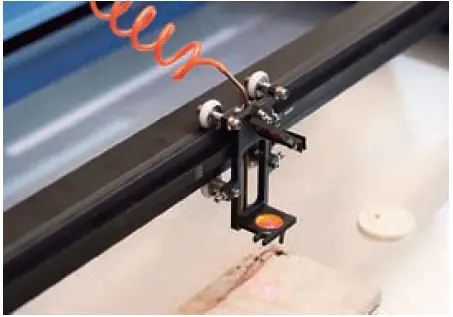
Fig.1 Synchronous belt transmission
Typically, the drive wheel and servo motor also use a reducer for torque amplification when using the synchronous toothed belt (shown in Figure 1).
The timing synchronous belt has advantages such as fast speed, low noise, low cost, no need for lubrication and easy maintenance. However, it has disadvantages such as differences in rigidity, easy wear, low precision and small driving force. Therefore, it is suitable for low-cost, light-load and high-speed applications.
It is widely used in small and medium power laser cutting and marking equipment, which is low in cost and does not require high precision.
For high-speed and high-precision laser cutting equipment, the running accuracy of the synchronous belt is obviously not enough, and the load capacity is also not enough to directly drive heavy, rigid and large-sized moving parts. The most common arrangement is to place it in the transmission chain of high-speed ball screw and other institutions to form a two-stage transmission.
In the basic product of high-power laser cutting machines, the Z-axis drive is directly driven by the synchronous belt (as shown in figure 2).
Fig.2 The upper and lower movement of the z-axis section cutting head is driven by the synchronous belt.
For a two-dimensional machine with a three-axis system, the z-axis transmission accuracy usually does not affect the cutting accuracy and quality.
This design intelligently takes advantage of the benefits of synchronous belt transmission such as fast speed, low noise and low cost, while avoiding the disadvantage of low accuracy.
Ball screw drive
The ball screw (shown in FIG. 3) is a drive mechanism commonly used in various types of cold processing equipment. This technology has been widely developed and its cost is reasonable.
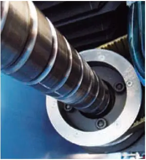
Fig.3 Rotating ball screw nut
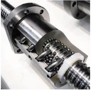
Fig.4 Internal structure of the ball screw
The ball screw is a drive mechanism widely used in various cold processing equipment because of its ability to achieve zero backlash and maintain high transmission efficiency and rigidity through the application of prepressure or feed excursion. It can also achieve up to 95% transmission efficiency, making it an ideal driving method for a variety of applications.
However, using a ball screw in a laser cutting machine has limitations. Due to its weight, the ball screw is typically supported on two ends, resulting in a certain tilt in the center of the screw. This deflection can cause instability, especially at high speeds.
To solve this problem, thicker wire rod must be selected, which can increase manufacturing costs and place a heavier load on the motor. Therefore, the ball screw is an excellent choice for drive methods in laser cutters with a short stroke and small cutting area, as its accuracy, speed and cost are suitable for such applications.
However, for long stroke (≥3m) and high speed (≥60m/min) applications, integrating a ball screw driver is not the ideal method. While it is possible to achieve long stroke, high speed applications with a ball screw by rotating the nut or adding an auxiliary support device to prevent nut movement, such solutions are technically challenging and face significant challenges in terms of cost and reliability.
Gear and rack
The rack is commonly combined with planetary gear reducers or turbine worm reducers to match inertia and amplify torque. Some manufacturers also use torque motors for direct connection to the final gear.
High-precision racks are similar to ball screws in terms of positioning accuracy, as they can easily achieve a positioning accuracy of 0.03 mm/m, which is higher than the accuracy required for laser cutting.
Regarding speed, the gear and rack can achieve various combinations by changing the number of gear teeth and the speed ratio of the reducer. There is no limit to the ball screw's critical speed, making it easier for servo motors to work in high speed ranges and shortening the equivalent pitch to drive large inertia loads with smaller motors.
The theoretical limit of gear and rack can reach 400m/min, and it is easy to reach speeds of up to 100m/min.
Both straight teeth and crooked teeth are widely used in laser cutting machines. Crooked teeth are easier to install and detect, and can achieve higher operating accuracy under the same machining accuracy and installation conditions.
The advantage of crooked teeth is that they have a slightly higher load capacity under the same load, which makes the design more compact. Furthermore, the most significant difference between the two types is that the noise from the crooked teeth is relatively low at high speeds, providing a better operating environment for operators.
As long as the base can maintain sufficient precision and rigidity, the rack's travel can be extended almost indefinitely, with manufacturing costs increasing linearly.
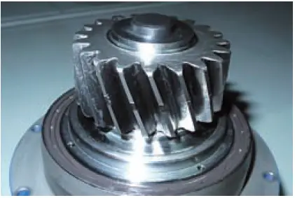
Fig.5 Laser welding gear drive
However, the rack (Figure 6) also has its disadvantages. For example, it requires higher machining precision of the base and the installation process is more complicated compared with the ball screw. Additionally, due to the need for lubrication and thermal expansion, there is a specific backlash between the rack and pinion, while the planetary reducer in the drive chain has a small but noticeable backlash. The accumulation of these factors makes it difficult for the rack to achieve a zero-backlash operation effect, as in the case of a ball screw.
The use of dual motors, dual reducers or other elastic means can compensate for these disadvantages, but this results in unfavorable weight, cost and drivability indicators.
However, fortunately, with reasonable design and precise construction, a two-stage rack can well meet the precision requirements of conventional laser cutting at present. And there is still ample room for development.
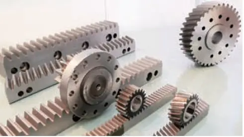
Fig.6 Precision rack of laser cutting machine
With comprehensive consideration, the precision of the rack and pinion is able to meet the demands of laser cutting. This drive system offers flexibility in selection, maximizes servo motor performance, and makes it easy to achieve high dynamic performance.
As a result, rack drive has become the main solution for high-power laser cutting machines.
Linear motor
Linear motors, as a new driving mode, have been widely used in various NC equipment, including laser cutting machines.
Following are some of the clear advantages of linear motors:
(1) There is no mechanical contact and the transmission is generated in the air gap, resulting in no direct wear of the drive component.
(2) The stroke is theoretically unlimited and the performance of the linear motor is not affected by changes in the route.
(3) It can provide a wide speed range from several micrometers to several meters per second, with high speed being a prominent advantage.
(4) The acceleration is significant, up to 10g.
(5) High precision and repeatability are achievable. As the intermediate link is eliminated, the accuracy of the system depends on the position sensing element. With an appropriate feedback device, the final operating accuracy can reach the sub-micron level. This feature has found wide application in the field of precision laser cutting.
Thank you for requesting a content review. Here is the revised version:
Due to the advantages of linear motors, laser cutting machines with linear motors have set industry speed and acceleration records. It appears that the linear motor may eventually replace ball screws and racks as the primary drive mechanism for laser cutting machines.
However, with the widespread adoption of linear motor drives, new problems have arisen that were not previously anticipated:
(1) The linear motor consumes a lot of energy, especially at high loads and accelerations. The instantaneous current from the machine can significantly overload the shop's power system.
(2) High vibration occurs due to the low dynamic stiffness of the linear motor, which is unable to dampen the damping effect, leading to resonant vibrations at high speeds in other parts of the machine.
(3) The linear electric motor fixed to the bottom of the bench generates significant heat. The installation position does not favor natural heat dissipation, posing a significant challenge to the thermostatic control of the laser cutter.
(4) The motor shaft driven by the linear motor, especially the vertical shaft, must be equipped with an additional locking mechanism such as a guide clamp to ensure safe operation. This increases the cost and complexity of the laser cutter.
(5) The linear motor generates a strong magnetic field and attracts iron filings, which can be problematic in laser cutting environments with a lot of tiny metal powder that is melted and cooled by the laser. Maintaining internal cleanliness becomes a challenge.
Although foreign manufacturers such as MAZAK and AMADA have introduced full or partial linear motorized models to demonstrate their technical competence and set speed records, high prices and modest returns have made the market less receptive to this type of model.
Despite the excellent performance of the linear motor, practical issues remain in the application of laser cutting machine drives. Although it represents a trend in the future, there is still a lot of work to be done to solve these problems.
Conclusion
The search for excellent dynamic response is a common goal among many precision CNC machining equipment, especially for high-speed machining on laser cutting machines.
Achieving this goal requires vast and complex system design.
In essence, a good load (light, high rigidity, small inertia), a robust drive chain (high rigidity, fast response, low backlash, high efficiency, low friction) and a powerful motor (inertia matching, fast response, strong torque ) are accurate.
However, most of these factors conflict with each other, making it necessary to select them scientifically and design the drive system reasonably.
Each manufacturer has its own unique understanding and approach to selecting and balancing these factors to achieve the best results.