Pull boxes are used along with conduit to simplify wiring installation, hence their name. They are made from sheet metal, cast metal, or nonmetallic material and provide a way to pull conductors long distances without placing excessive strain on the wire or insulation. Pull boxes allow long runs of wiring to be installed at shorter intervals and can be used for straight and angled pulls.
Although they look the same as junction boxes, junction boxes do not have wiring connections inside them. They are just access points for pulling and feeding conductors into a raceway system. Its use is mandatory in ducts where the number of bends between outlets exceeds the maximum number allowed by the NEC (National Electric Code).
Traction box sizing is based on the size and number of conductors, as well as the number of tracks and their diameter. For conductors 4 AWG and larger, pull boxes and junction boxes must be sized in accordance with NEC Article 314.28. This post will provide an overview of the sizing rules for the most common types of traction, along with an example calculation.
Straight pulls
In straight pulls, the conduit enters and exits on opposite sides of the box. The depth of a straight pull box is determined by the size of the largest conduit and the space required by the locknuts and bushings. On the other hand, the length of the pull box must be at least eight times the diameter of the largest conduit:
- Suppose a junction box has four runs of conduit and the largest diameter is 4”
- Minimum box length = 8 x 4” = 32”
Angled pulls, U-pulls and splices
Conduit boxes and bodies containing 4 AWG or larger conductors and containing U-angles or handles shall be sized in accordance with the specifications in NEC Article 314.28(A)(2).
Angular pulls
For angular traction, the distance between each track entry within the box and the opposite wall of the box shall be the sum of the following:
- Six times the commercial size of the biggest consecutive track.
- The sum of the diameters of all other lane entries on the line.
Suppose a traction box has a 90° turn with three tracks, with diameters of 4”, 2” and 2”. The calculation procedure would be as follows:
- Six times the largest track diameter = 6 x 4” = 24”
- Sum of all other track diameters = 2” + 2” = 4”
- Total = 24” + 4” = 28”
Furthermore, the straight distance between the entry and exit points of each circuit must be six times the diameter of the respective conduit. In the example above, the necessary separations are:
- Separation for circuits in 4” conduit = 6 x 4” = 24”
- Separation for circuits in 2” conduit = 6 x 2” = 12”
Looking for electrical engineering services?
U-handles
When conductors enter and exit the same wall, the distance from where the tracks enter the opposite wall is calculated with the same procedure used for angled bends:
- Six times the commercial size of the biggest consecutive track.
- The sum of the diameters of all other tracks on the same wall and line.
Note that entry and exit points are counted separately for each driver route. If a circuit uses 3” conduit and uses a half-turn pull box, the procedure is as follows:
- Six times the largest track diameter = 6 x 3” = 18”
- Sum of all other track diameters = 3”
- Total = 18” + 3” = 21”
The straight-line distance between the entry and exit point is equal to the angle bends: six times the diameter of the conduit. In the example above, the required separation is 18” (6 x 3”).
Combination boxes with straight and angled handles
When there are straight and angled pulls on the same box, calculations must be performed according to both sets of rules, applying the largest resulting dimension. Assume the following traction combination:
- Straight traction with 2” track
- Angular traction with 3” track
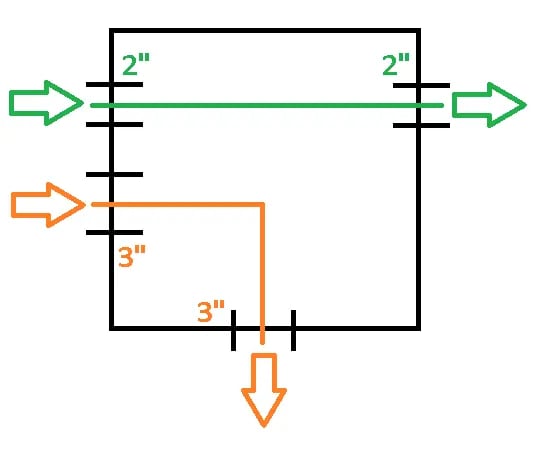
Height Calculation
This calculation is simple because there is only one possibility: six times the largest channel plus the sum of the rest. There is only one clue, so it is multiplied by six and nothing else is added.
- Height = 6 x 3” = 18”
Width calculation
In this case there are two possibilities, so both calculations are performed and the largest value is chosen. Option #1 is 8 times the diameter for straight pull and option #2 is 6 times the largest channel plus all other diameters.
- Width (Option 1) = 8 x 2” = 16”
- Width (Option 2) = 6 x 3” + 2” = 18” + 2” = 20”
Pull box dimensions
This pull out box must be 18” high and 20” wide. For angle pull, the distance between the inlet and outlet is 18” (six times the conduit dimension, which is 3”).
Importance of Design Procedure
While pull out boxes are convenient, remember that they require materials and labor and can increase the cost of the project if used excessively. The best recommendation is to hire a qualified design company to optimize the electrical layout, ensuring that junction boxes are only used when necessary.
Energy efficiency also helps to optimize electrical installation costs. A smaller load requires smaller wiring, which in turn uses smaller diameter conduit and fixtures. The price difference may not be large for a single circuit, but it adds up quickly on a large project such as a high-rise building.
Editor's Note: This post was originally published in November 2017 and has been reworked and updated for accuracy and comprehensiveness.