USB communication

Figure 1: Image showing USB communication
While C communication in USB we consider three parts-
a) Host which can be a computer/PC/laptops
b) USB cable and connector
c) Peripheral devices, e.g. Keyboards, mouse, audio player, etc.
USB systems consist of a personal computer (PC) known as the host and several peripheral devices such as a mouse, keyboard, and audio system. The host itself contains two components, the host controller and the root hub. A host controller is a hardware component contained within a host computer. The Host controller converts the data into the language understandable by the OPERATING SYSTEM and also manages the communication on the bus. The USB host controller has a built-in hub called root hub . A hub is a common connection point that allows multiple devices to connect on the network. A hub contains several ports . The root hub connects the host controller(s) to the peripheral device and acts as the first interface layer for USB in a system. The ports visible on the back panel of the system are the root hub ports. These ports are part of the root hub and in turn can be connected to the external hub, thus increasing the number of USB devices that can be connected to the host. An external hub can be used to extend connections to a maximum of 127 devices.
Whenever a USB device is connected or disconnected, it is first detected at the root hub which in turn passes information to the host controller. USB is a half duplex protocol where all data is passed through a two-wire interface called D+ (D plus) and D- (D minus).
The host is responsible for the following tasks:
1. Detect attachment and removal of USB devices
2. Provide and manage power for connected devices
3. Monitor activity on the bus and begin the enumeration process
4 . Manage data flow between host and devices.

Figure 2: Schematic image showing various devices connected to USB
When we discuss data transfer over USB, we always use the host's point of view as a reference. For example, if there is an IN transfer, it means the host will receive the data. An OUT transfer means that the host will transmit data.
USB Communication Part I (tubes and endpoints)
TUBE CONCEPT AND END POINT
Ports are used to connect peripheral devices like mice, keyboards, or audio devices to them. Each device is assigned a specific address used during the communication process by the host. These devices are connected to the root hub and in turn to the host via pipes. A pipe is a logical connection between the host and the endpoint and is used by client software to transfer data. It defines several parameters such as direction of data flow, length of bandwidth allocated to the device, and what type of transfer will occur. There are two types of pipes in USB: one is the stream pipe and the other is the message pipe.
· Flow tubes – These are one-way communication tubes used for most data transfers. These pipes do not have a defined USB format. We can send any type of data from one end and retrieve it from another end. Data flows sequentially and has a predefined direction, IN or OUT. Flow tubes support bulk, isochronous, and interrupt transfers and are controlled by the host or the device.
· Message channels – These are two-way communication channels and are used only for sending/receiving short messages. These tubes have a defined USB format. They are controlled by the host and initiated by request sent by the host. Data is transferred in the desired direction as per the request. They only support control transfers.
Once we understand channels, we will learn about various types of data transfer. Depending on the type of data we need to decide which type of pipe to use.
There are four different types of USB data transfer.
1. Transfer of control – Used to send commands to devices to carry out queries. This transfer uses messaging channels.
2. Interrupt transfers – It is used to send small amounts of data that require a guaranteed minimum delay. It uses flow tubes.
3. Bulk transfer – It is used to transfer large amounts of data with no time guarantee and uses Stream pipes
4. Isochronous transfers – is used for transferring data that requires a fixed delivery rate as it is capable of fixed bus bandwidth and lack of error correction. Since there is no error correction, there is no delay in data transfer. These transfers use Stream pipes.

Fig. 3: An Overview of USB Communication
Between the device and the host there is an addressable buffer which is known as the endpoint. An endpoint is an electrical terminal that usually consists of a set of memory registers that temporarily stores data on USB peripheral devices upon input or output. A terminal stores data received from the host and maintains data to be transmitted to the host. A USB device can have multiple terminals and each terminal has a channel associated with it. Each terminal is accessed with a host-assigned device address and a device-assigned terminal number. Endpoints often come in pairs, for example, Endpoint 1 In and Endpoint 1 Out. A set of endpoints, Endpoint 0 In It is Endpoint 0 Output is always on and is used for basic commands to all USB devices.

Figure 4: Image showing the relationship between USB host and devices
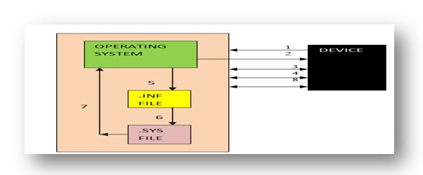
The next figure shows the entire USB system. Let's try to understand what exactly happens when a peripheral device is connected to the USB port and what are the processes happening between the host and the peripheral device.

Figure 5: Block diagram showing the complete USB system
USB Communication Part II
ATTACH EVENT
When any device is connected to the PC's USB port, it, in turn, is connected to the root hub. This is known as an attach event and removing the device is known as a detach event. The device is detected by the root hub by monitoring port voltages. A hub has a pull down resistor on the D+ and D- lines. In the initial condition, D+ and D- are at the same 0V potential due to the 15kohm resistors found on the host side. Now when a cable is connected a pull up resistor is at D+ or D- as specified by the device manufacturer so if voltage change is detected on D- line then it is a low speed device and the change of voltage is at D+, it is a high speed device. Once the speed has been detected, the ENUMERATION process begins.
ENNUMERATION- It is a process by which the host assigns an address to each peripheral device that allows communication with USB devices.
The enumeration process can be divided into 2 phases: Phase 1 where the host learns about the newly arrived device by reading the descriptors and loads the appropriate device driver & PHASE 2 where the device driver configures the device and prepares it for data transfer. data .
STEP 1-ASSIGNING ADDRESSES
The host recognizes the newly connected device through changes in port voltage. All devices on the USB bus will be assigned a unique host address. But when any device starts communicating with the host, it always starts communicating using address 00H. A device terminal is a uniquely addressed part of a USB device that is a source or sink of information.
After the initial information about the device is collected by the host, it issues a request to the hub to reset the newly connected device. This is done by pulling the D+ and D- lines to the ground. Holding these lines low for more than 2.5 knots causes the reset condition. This reset state is maintained for 10 ms by the hub. A new address is assigned to each peripheral device once brought out of the reset state and the device responds to the hosts request using control transfers via address 00h. USB devices are enumerated sequentially rather than simultaneously.
STAGE 2- COLLECTION OF INFORMATION FROM DESCRIPTORS
In the next part, the host starts to learn more about the device using device descriptors. Information about a USB device is stored in segments of its ROM (read-only memory). Each time a peripheral is connected, the host will request a series of data structures from the device that will inform the host of its capabilities. These data structures are called “descriptors”. There are four types of descriptors in USB, each with a specific function. The figure below gives a clear picture of the descriptors.

Figure 6: A closer look at USB descriptors
From the above figure we have the device descriptor, next is the configuration descriptor followed by the interface and lastly the endpoint descriptor. Therefore, after the device descriptor, host requests for configuration descriptor, interface descriptor, and endpoint descriptor. Each of these descriptors contains information necessary for communication between host and peripheral devices, as described below.
Device descriptors – Contains general information about the device that is globally accepted and common everywhere. A USB device can only have one device descriptor. For example, when a camera is connected to the USB port, device descriptors will send host information such as USB specification, supported protocols, vendor ID, pin ID, number of configurations a device can adopt, and serial number if gift.
Configuration descriptors -Consider a multifunctional peripheral device such as a video camera with an internal microphone. Sometimes we just use a video camera, like when we click photos, or we use a microphone to record sound. In some other situation where we are interested in video recording we will use camera and microphone. Both arrangements will have different requirements for their operation and are called configurations. The first configuration requires less energy and the second will require more energy. This is just one example of where there are different settings on a single device; There may be other devices that will have another configuration. A configuration can be viewed as a collection of peripheral resources. Thus, configuration descriptors specify values such as the amount of power a given configuration uses, secondly, whether it is self-powered or bus-powered, and the ultimate number of interfaces involved.
· Interface descriptors – With the same example of a multifunctional device such as a video camera with internal microphone, we can have three alternative configurations.
|
Camera activated |
|
Microphone on |
|
Camera and microphone activated |
Each of these different settings is present in three different interfaces. Group of endpoints forms an interface. An interface can group zero, one or multiple endpoints. We already know that endpoints are temporary memory records that store information about the device. The endpoints of each interface will store different types of information specific to that configuration. The interface descriptor specifies the number of endpoints required by a device resource.
Endpoint descriptors – Endpoint descriptors contain information about the I/O direction (IN which is from the device to the host or OUT which is from the host to the device), the type of transfer (Control, Bulk, Interrupt, or Isochronous) and the maximum supported packet size. Devices publish endpoint descriptors to allow clients to query which endpoint is available and what characteristics they have.
ASSIGNING AND LOADING THE DEVICE DRIVER
Once the host has gathered all information about the device, it needs to load a device driver to successfully communicate with peripheral devices. The device driver it is a computer program that operates or controls a specific type of device connected to a computer. A driver typically communicates with the device across computer bus to which the hardware connects. When a program is called to run a specific peripheral device, the driver issues commands to the device. After the device sends data back to the driver, the driver can start routines in the original program being called. Drivers are hardware dependent and operating system specific. An operating system has a broad group of I/O devices with similar characteristics and will use class-specific drivers to interact with the devices.

Figure 7: Image showing various driver classes
A class specification defines functions that describe how data will be transferred. They also define the number and type of buffers supported by the class. The classes facilitate the development of device drivers and firmware in a standardized way. USB devices that share many attributes or request similar services are grouped into the same class.
If a device has previously been enumerated, the operating system uses its registry to search for the appropriate driver. Once a driver is identified, the host can request additional descriptors specific to the device class or request that the descriptors be resent.
For example, in the case of Windows, it uses its INF files to find a match for the devices' product ID and vendor ID. One INF file is a configuration information file, it is a simple text file used by Microsoft Windows for installing software and drivers. The device may also release version numbers that can be used optionally. If Windows cannot find a match, it looks at the driver from a different perspective, looking for a match to any classes, subclasses, and protocols retrieved from the device.
LOADING THE APPLICATION SOFTWARE
Once the specific driver is loaded, data exchange between the host and the peripheral device begins. Application software associated with a specific type of device can be used to improve the device's performance. Graphics software, media players, business software are some examples of application software.
Cables and Connectors
USB cable and connectors
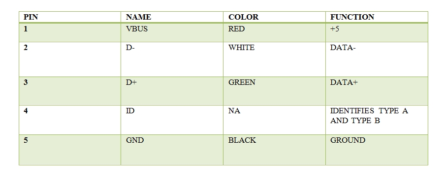
From an external overview, USB has two components: cables and connectors. These connectors connect devices to a host. A USB cable consists of several components protected by an insulating jacket. Below the jacket is an external shield that contains a copper braid. Inside the external shield are several wires: a copper drain wire which is a twisted pair of cable, a VBUS wire (red) and a ground wire (black). An internal shield made of aluminum contains a twisted pair of data wires.

Figure 8: Cross-sectional view of USB cables and connectors
There is a D+ (green) wire and a D- (white) wire. On high-speed and high-speed devices, the maximum cable length is 5 meters. To increase the distance between the host and a device, you must use a series of hubs and 5-meter cables. Although there are USB extension cables on the market, using them to exceed 5 meters is against the USB specification. Low speed devices have slightly different specifications. Cable length is limited to 3 meters and low speed cables do not need to be twisted pair like USB twisted pair data wires. The voltage bus provides a constant 4.40V – 5.25V supply to all devices and the data lines provide up to 3.3V. The reason for using the D+ and D- differential signal is to reject signal noise. common mode. If the noise is coupled to the cable, it will typically be present in all wires of the cable. By using a differential amplifier in the USB hardware internal to the host and device, common mode noise can be rejected.
Now we move forward and learn more about connectors. The figure below shows the various types of connectors.

Figure 9: Multiple USB Ports Overview
There are many different types of USB ports and connectors available. The upstream connection always uses a Type A port and connector, while the device uses Type B ports and connectors. Initially, the USB specification included only the larger Type A and Type B connectors for devices, but later included Mini and Micro connections. These Mini and Micro connectors were initially developed for USB On-the-Go, which is a USB specification that allows devices that would normally act as slaves to become hosts, but were later adopted in devices due to their smaller size compared to type B.
1. Type A- It is used to connect the cable to the host device, also known as the upstream end. They have a flat shape and four in-line connections.
two. Type B- It is used to connect the cable to the peripheral device and also known as the downstream end. They are square in shape and have two connections on either side of the center.

Figure 10:
Description table of Micro A and Micro B type connectors.
Benefits of USB
BENEFITS OF USB
USB brings benefits to everyone. It helps reach the entry-level PC consumer by overcoming usability barriers through easy peripheral installation. The end user has a more rewarding and productive experience.
Below is a table of the current features USB has to offer:

Figure 11: Table describing the Micro A and Micro B type connector


