Note: It is recommended that you follow this series of VHDL tutorials in order, starting with the first tutorial .
In the previous tutorial we designed clocked SR latch circuits using VHDL (which is a very high-speed integrated circuit hardware description language).
For this project, we will:
- Write a VHDL program to build a D flip-flop circuit
- Check the program output waveform (digital circuit) with the truth table of this flip-flop circuit
The D flip-flop circuit 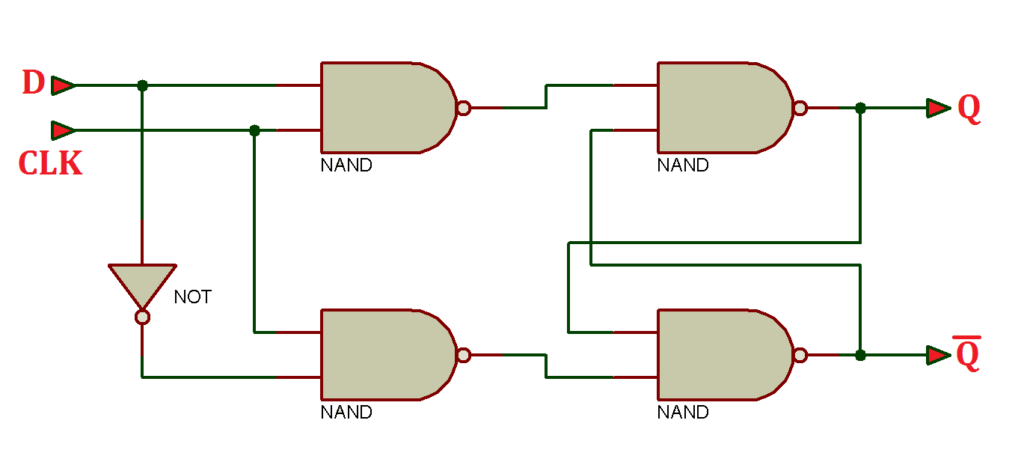
Truth table

Now let's write, compile and simulate a VHDL program. Then we will get the waveform output and check it with the given truth table.
Before you begin, be sure to review the step-by-step procedure provided in VHDL Tutorial – 3 to properly design the project, as well as edit and compile the program and waveform file, including the final output.
For this tutorial, we use a behavioral modeling style to write the VHDL program that will build the flip-flop circuit. This is the preferred modeling style for sequential digital circuits.
VHDL Program
ieee library;
use ieee.std_logic_1164.all;
entity D_flip_flop is
port (clk,Din: in std_logic;
Q: out std_logic;
Qnot: out std_logic);
end D_flip_flop;
DFF_arch architecture of D_flip_flop is
to start
process (clk,Din)
to start
if(clk'event and clk='1′) then
Q <= Noise;
Qnot <= (not Din);
end if;
end of the process;
end DFF_arch;
To refresh your memory on how this works, read the first two VHDL tutorials ( 1 and 2 ) in this series.
Next, compile the above program, creating a waveform file with all the necessary inputs and outputs listed, and simulate the project. You should get the following result…
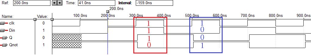
Simulation waveform
As shown in this figure, there are two cases highlighted in red and blue.
- Case 1: when clk=1 and Din=1 -> Q = 1 and Qnot = 0
- Case 2: when clk=1 and Din = 0 -> Q=0 and Qnot = 1
This program for the D flip-flop circuit looks quite simple. So let's complicate things a little more by adding two more input signals:
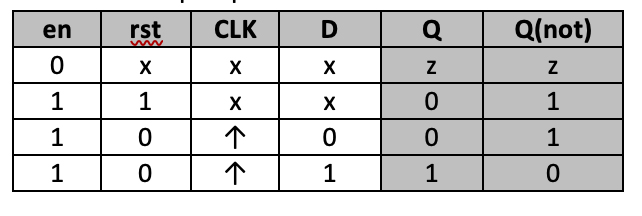
1. Reset: Reset high input activates, so when the input is '1', the flip-flop will be reset and Q=0, Qnot=1
2. Enable: Enables the input to the flip-flop circuit, so if it is set to '0', the flip-flop will be disabled and both outputs will be at high impedance (where '1' is when the flip-flop operates normally)
Truth table for the D flip-flop
Now, here is the D flip-flop program with the enable and active high reset inputs.
ieee library;
use ieee.std_logic_1164.all;
entity D_flip_flop is
port (clk,Din,rst,en : in std_logic;
Q: out std_logic;
Qnot: out std_logic);
end D_flip_flop;
DFF_arch architecture of D_flip_flop is
to start
process (clk,en,Din,rest)
to start
if(pt='0′) then
Q <='z';
Qnot <= 'z';
elsif(rst='1′) then
Q <='0′;
Qnot <='1′;
elsif(clk'event and clk='1′) then
Q <=Din;
Qnot <= not Din;
end if;
end of the process;
end DFF_arch;
By compiling and simulating the above program, you will get the following waveform output…
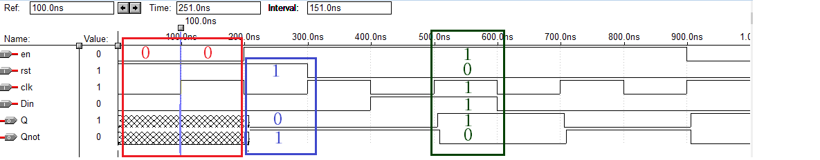
Simulation waveforms
As shown in this figure, there are three cases highlighted in red, blue, and green.
- Case 1: When en = 0, both outputs Q and Qnot are high impedance (z)
- Case 2: when en=1 and rst=1 -> Q=0 and Qnot=1 (the flip-flop is reset)
- Case 3: when en=1, rst=0 and Din=1 -> Q=1 and Qnot=0
In the next tutorial we will build a JK flip-flop circuit using VHDL.