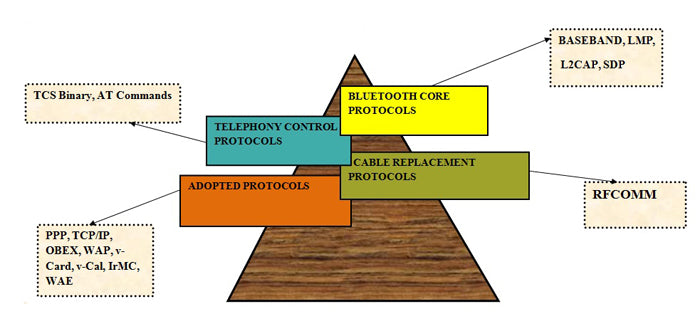
The Bluetooth protocol is made up of several protocols that can be divided into four categories. Each of these protocols is responsible for a specific type of task and is independent. In the previous article about Bluetooth we talked about the basic terms, specific values of power, frequency, range and much more. The concept of master networks, slaves, Pico networks and dispersed networks forming ad-hoc networks. This part of Bluetooth will deal with the protocols responsible for the functioning of Bluetooth technology. The four categories these protocols are divided into are shown below:

Fig. 1: Block diagram explaining Bluetooth protocols
Bluetooth main protocols
Baseband
Baseband allows radio frequency link between Bluetooth devices to form a Pico-net. Information is exchanged in packets over Bluetooth. A packet is a unit of binary data that carries information required by the user and that can be routed through a computer network. Both circuit switching and packet switching are used to transfer the packets in the network. Packet-switched networks move data in small, separate blocks – packets – based on each packet's destination address. When received, the packets are reassembled in the proper sequence to form the message. Circuit-switched networks require dedicated point-to-point connections during calls and are generally used over telephone lines for exchange.
The Link Manager Protocol
The link manager protocol is responsible for establishing a link between two Bluetooth devices. This protocol layer is responsible for security issues such as authentication, encryption, exchange and verification of link and encryption keys.
Logical Link Control and Adaptation – Layer (L2CAP)
The Bluetooth logical link adaptation and control layer supports higher-level multiplexing, packet segmentation and reassembly, and communication and quality of service groups. This layer is not responsible for reliability and uses ARQ to guarantee it.
Service Discovery Protocol (SDP)
SDP is the basis for service discovery across all Bluetooth devices. This is essential for all Bluetooth models because with the information from the SDP device, the services and characteristics of the services can be queried and after that the connection between two or more Bluetooth devices can be established. Other service discovery protocols like Jini, UpnP etc. in conjunction with the Bluetooth SDP protocol.
Bluetooth protocol categories
Cable Replacement Protocol
RFCOMM
RFCOMM protocol is used for cable replacement option in Bluetooth. It is a simple transport protocol with additional provisions to emulate the nine RS232 serial port circuits in the L2CAP part of the Bluetooth protocol stack. Supports large base for applications that use serial communication. It provides reliable data flow, multiple connections, flow control and serial cable line configurations.
Telephony Control Protocol
Specification (TCS binary)
The TCS binary protocol defines call control signaling for establishing voice and data calls between two Bluetooth devices. It is a bit-oriented protocol.
The Host Controller Interface (HCI)
HCI provides a command interface to the baseband controller, link manager, and access to hardware status and control registers. The interface provides a uniform method of accessing Bluetooth baseband resources. The host control transport layer removes transport dependencies and provides a common driver interface. Three interfaces are defined in the main specification: USB, RS-232 and UART.
ADOPTED PROTOCOLS
PPP, TCP/IP
PPP, TCP, UDP, and IP are standard Internet protocols defined by the IETF. They are used as lower layer protocols to transport packets or datagrams on their specified IP addresses. OBEX
OBEX is a session protocol defined by IrDA. This protocol is also used by Bluetooth, thus allowing the application to use Bluetooth radio or IrDA technologies.
WAP/WAE
Bluetooth can be used as a transport technology for transport between a WAP client and a nearby WAP server. WAP operates over the Bluetooth stack using PPP and the TCP/IP protocol suite.
Each of these protocols is organized neatly as layers, one above the other, forming a protocol stack. A pile is a pile of objects or things arranged in a neat manner.
Hence, Bluetooth is defined as layered protocol architecture because each layer supports the layer above and below it. The complete protocol stack consists of Bluetooth-specific protocols that are clearly defined or developed for Bluetooth, such as LMP, and non-Bluetooth-specific protocols, which are designed to allow reuse of existing protocols for multiple functions. Non-specific protocols can be used with many other platforms like WAP, UDP AND OBEX. They were used to accelerate the development of the Bluetooth protocol at higher layers, while adapting to work with Bluetooth devices and ensuring interoperability. The outline of the Bluetooth layers and protocols associated with it is shown below.

Figure 2: An overview of various Bluetooth layers and associated protocols

Figure 3: Block diagram showing various Bluetooth layers and functions
Each of the layers specified above is important in Bluetooth communication and has an internal circuit to perform the desired task. In this section we will cover the internal details of all layers.
Internal details of Bluetooth protocols
Bluetooth Radio
Bluetooth radio provides an electrical interface for transferring packets on a modulated carrier frequency using wireless carrier services like CDMA, GSM. The radio operates in the 2.4 GHz band. It requires an efficient antenna for transmission and reception, an RF front-end that includes an UP converter, down converter, power controller, GFSK modulator and a transmitter/receiver switch.
Bluetooth Radio Modem IC
The radio modem performs GFSK modulation and demodulation, symbol recovery, and frame timing. It features a fully integrated radio transceiver and frequency hopping synthesizer on a single chip. In the real-life system, the signals traveling between the antennas are of much higher frequency and are of known radio frequency. Therefore, to decrease the frequency range, analog circuits are typically used for downconversion at the receiver end and similar upconversion at the transmission end. An analog to digital converter is present on the receiver side to bring the signal into the digital domain. It is then passed to the GFSK demodulator. The Bluetooth modulation scheme is GFSK (Gaussian Frequency Shift Keying). Gaussian Frequency Shift Modulation (GFSK) is a modulation method for digital communication found in many standards such as Bluetooth, DECT, and Wavenis. It minimizes trans-receiver complexity by using one for positive frequency offset and zero for negative frequency offset. The IC also contains a frequency hopping synthesizer on the same chip.

Figure 4: Block diagram of various functions in the Bluetooth radio modem
BAND AND RADIO CHANNELS
The Bluetooth radio operates in the 2.4 GHz ISM band. In the US and Europe, an 83.5 MHz band is available. There are 79 channels spaced 1 MHz apart. Japan, Spain, and France only use 23 channels spaced 1 MHz apart .
Baseband
This is the most important part of the Bluetooth protocol. Baseband is the physical layer of Bluetooth that manages physical channels and links. The baseband sits on top of the Bluetooth radio. Bluetooth link controller IC is used to implement the baseband protocol and functions and interfaces with the Bluetooth radio modem IC. The link controller wisely chooses the links and channels to be used and improves the performance of applications. It synchronizes with the layer above i.e. the link manager to perform link level routines such as link connections and power control. On the receiver side, it performs error detection, data whitening, hop selection and Bluetooth security. The controller hardware performs the basic functions such as repetitive paging, querying, and page and query scans. It also provides a USB and audio interface for the host system.

Figure 5: Diagram showing various functions of the baseband layer in Bluetooth
The baseband also manages links, handles packets, and does paging and querying to access and query Bluetooth devices. The transmitter applies time division multiplexing in addition to frequency division (frequency hopping). In normal connection mode, the master starts in even slots and the slave uses odd slots. There are two types of links: ACL and SCO links. A link is a two-point, end-to-end circuit that connects end users and allows them to communicate even when two separate physical paths are used. Let's move on to the ACL and SCO links used in the baseband layer.
ACL links – connectionless asynchronous
ACL links are a point-to-multipoint link between the master and all slaves participating in the piconet. ACL links carry data information and only a single link can exist. Retransmission of data packets is allowed on ACL links.
SCO links – synchronous connection link
SCO links are a point-to-point symmetric link between a master and a single slave. It can carry both data and voice information, but it primarily carries voice information. The master can support up to two or three SCO links. SCO packets are never retransmitted.
LOGICAL CHANNELS
A channel is a high-speed, two-way communication between two devices. For example, a computer and its peripheral device. There are five different types of channels present in Bluetooth that can be used to transfer different types of information. The LC (control channel) and LM (link manager) channels are used in the link-level part of the communication. UA, UI and US are used to transport asynchronous, isosynchronous and synchronous user information.
BLUETOOTH ADDRESS
An address is a name or token that identifies a component on the network. There are basically four device addresses as shown below.
|
BD-ADDR |
48-bit Bluetooth device address (IEEE802 standard). It is divided into LAP (lower part of 24-bit address), UAP (upper part of 8-bit address) and NAP (non-significant part of 16-bit address). |
|
AM-ADDR
|
3-bit active member address. The all-zero AM_ADDR is for broadcast messages. |
|
PM-ADDR |
8-bit member address assigned to parked slaves |
|
AR-ADDR |
It is used by the parked slave to determine whether it is allowed to send access messages. |
A breakdown of Bluetooth address fields:
|
24 |
8 |
16 |
|
LAP |
|
|
UAP |
NAP |
BLUETOOTH PACKAGES
Data in piconets is transmitted in packets. A package is shown below.
|
ACCESS CODE (72) |
HEADER (54) |
PAYLOAD (0-2745) |
The shortcode is used for time synchronization, paging and querying. There are three different types of shortcodes; Channel access code that identifies a piconet; The device passcode is used for paging and its responses and query passcode are for query purposes. The header contains packet acknowledgment, packet numbering, flow control, slave address, and error checking information. The packet payload represents the voice field, the data field, or both. There are five common types of packages, four SCO packages and seven ACL packages.
|
MR. NO. |
NAME |
TYPE |
DESCRIPTION |
|
1
|
COMMON |
I WENT |
Uploads device access code (DAC) or query access code (IAC). Occupies one slot. |
|
two |
COMMON |
NULL |
The NULL packet is used to obtain link and flow control information and has no payload. Occupies one slot. Not recognized. |
|
3 |
COMMON |
SURVEY |
No payload. Recognized. Used by the master to query slaves to see if they are active or not. Occupies one slot. |
|
4 |
COMMON |
ESF |
A special control packet to disclose the Bluetooth device address and sender clock. Used in page master response, query response, and frequency hopping synchronization. |
|
5 |
COMMON |
DM1 |
To support control messages on any type of link and also carry regular user data. Occupies one slot . |
|
6 |
SCO |
HV1 |
Carries 10 bytes of information. Typically used for voice transmission. 1/3 FEC coded. Occupies one slot. |
|
7 |
SCO |
HV2 |
Carries 20 bytes of information. Typically used for voice transmission. 2/3 coded FEC. Occupies one slot. |
|
8 |
SCO |
HV3 |
Carries 30 bytes of information. Typically used for voice transmission. Not FEC encoded. Occupies one slot. |
|
9 |
SCO |
DVD |
Combined data-voice package. Voice field not protected by FEC. Data field 2.3 FEC encoded. The voice field is never retransmitted, but the data field can be. |
|
10 |
LCA |
DM1 |
Carries 18 bytes of information. 2/3 coded FEC. Occupies one slot. |
|
11 |
LCA |
DH1 |
Carries 28 byte information. Not FEC encoded. Occupies one slot. |
|
12 |
LCA |
DM3 |
Carries 123 bytes of information. 2/3 coded FEC. Occupies three slots. |
|
13 |
LCA |
DH3 |
Carries 185 bytes of information. Not FEC encoded. Occupies three slots. |
|
14 |
LCA |
DM5 |
Carries 226 bytes of information. 2/3 coded FEC. Occupies five slots. |
|
15 |
LCA |
DH5 |
Carries 341 bytes of information. Not FEC encoded. It occupies five vacancies . |
|
16 |
LCA |
AUX1 |
Carries 30 bytes of information. It resembles DH1, but without the CRC code. Occupies one slot. |
Bluetooth main protocols
ERROR CORRECTION
There are three types of error correction schemes: 1/3 rate FEC, 2/3 FEC, and ARQ scheme. At rate 1/3 each bit is repeated three times for redundancy, at rate 2/3 a polynomial is generated to encode the 10-bit code into a 15-bit code, and in the ARQ scheme a packet is transmitted until an acknowledgment is made. is received. It uses positive and negative commit values by setting appropriate ARQN values. IF the timeout is exceeded, the Bluetooth device releases the packet and proceeds to the next one.
FLOW CONTROL AND SYNCHRONIZATION
Bluetooth uses the concept of first in first out FIFO queues on ACL and SCO links for transmission and reception. The link manager fills the queues and the link controller empties them automatically.

Figure 6: Flow control and synchronization in the Bluetooth Core protocol
If the receive queues are full, flow control is used to prevent dropped packets and congestion. If data is not received, a STOP indication is transmitted by the receiver's link controller to the return packet header. When the transmitter receives the STOP indication it freezes its FIFO queues. Again, when the receiver is ready, it sends a packet that resumes the flow.
CONTROLLING STATES
State is the last known or current status of an application or process. Bluetooth operates in two states Stand by and Connect. There are seven substates that are used to add slaves or make connections in Pico-net. They are shown in the figure:

Figure 7: Wait state used in the Bluetooth Core protocol

Figure 8: Image showing the state of the connection controller used in the Bluetooth system
The standby state is the default low-power state used when there is no interaction between devices. In the connecting state, the master and slave can exchange packets using the channel access code.
|
NAME |
DESCRIPTION |
|
PAGE |
This substate is used by the master to activate and connect to a slave. The master sends page messages transmitting the device access code (DAC) of the slave on different hopping channels. |
|
PAGE CHECK |
In this substate, a slave listens for its own device access code (DAC) during the scan window. The slave listens on a single-hop frequency (derived from its page-skip sequence) in this scan window |
|
SLAVE'S RESPONSE |
The slave responds to the master's page message in this substate, which occurs if the slave correlates in the page scan substate with the master's page message. Slave enters Connection state after receiving FHS packet from master. |
|
MASTER ANSWER |
The master reaches this substate after receiving the slave's response to the page's message to it. Master sends an FHS packet to the slave and if the slave responds then the master enters Connection state. |
|
INVESTIGATION |
The query is used to find the identity of nearby Bluetooth devices. The discoverer unit collects the Bluetooth device addresses and clocks of all units that respond to the query message. |
|
INQUIRY VERIFICATION |
In this state, Bluetooth devices listen for queries from other devices. On this scanning device you can listen to the general query access code (GIAC) or dedicated query access codes (DIAC). |
|
RESPONSE TO SURVEY |
For investigation, only the slave responds, but not the master. The slave responds with the FHS packet that contains the slave device passcode, native clock, and some other slave information. |

Figure 9: Block diagram explaining how the connection is established between two Bluetooth devices
A connection between two devices follows a particular path. The first master asks about Bluetooth devices in range. If any Bluetooth device is listening to these queries (query scan substate), it will respond to the master by sending address and clock information (FHS packet) to master query response state 9. After sending the information, the slave starts listening the page messages from the master (page scan). Then, the master, after discovering the Bluetooth devices in range, can page these devices (page substate) to configure the connection. The slave in page scan mode will respond if paged by the master (slave response substate). The master after receiving the response from the slave can respond by transmitting the real-time master, BD-ADDR masters, parity bits and device class (FHS packet). Once they both receive this FHS packet, they will enter the connecting state.
CONNECTION STATE
A connection state begins with a packet sent by the master to check whether the slave has switched to the master's timing and channel frequency hopping. The slave can respond by sending any type of packet. Various connection states are
|
ACTIVATE |
In this mode, both the master and the slave actively participate in the channel by listening, transmitting or receiving. Master and slave synchronize with each other. |
|
SNIFF |
In this mode, the slave, instead of listening to the master's message to that slave, it sniffs the specified time slots for its messages. Therefore, it may go into sleep mode to save power. |
|
TO HOLD |
In this mode, a temporary device does not support ACL packets and goes into low-power sleep mode to allow activities such as page scanning, page querying, etc. |
|
PARK |
When the slave does not want to participate in Pico-net but still wants to synchronize on the channel, it goes into park mode, which is a low-power activity. |
Cable replacement protocols
SECURITY
Bluetooth security is very important to enable keyless doors and automatic billing superstores. At the link layer it is maintained by authentication and encryption. First, a device authenticates by issuing a challenge, and another device must then send a response to that challenge. The BD-ADDR and link key are shared between them. After authentication, encryption can be used for communication. There are four types of keys: combination, drive, temporary, and initialization.
Link manager and controller
The link manager is used to manage link security, configuration, and control. It communicates with another link manager to exchange information and control messages through the link controller using some predefined link level commands. Once the connection is configured, it can have up to three SCO connections created between it, or its mode can be changed, either to a low power mode or to a test mode (these are useful for certifying Bluetooth devices by authorities and for testing devices on a manufacturer's production line). When the connection is no longer needed, LMP may cause disconnection.
It has less support for higher layers, but can be improved by using a higher layer interface that allows you to run algorithms for mode management (park, hold, detect, wake), security management, QoS, etc. then the link manager can negotiate with another link manager about power control and both can enter the same mode according to the predefined algorithm
The Link Manager (LM) converts commands into operations at the Baseband level, managing the following operations.
1) Attach slaves to Pico-nets and allocate their active member addresses.
2) Break connections to disconnect Slaves from a Pico-net.
3) Configuring the link including Master/Slave switches
4) Establishment of ACL and SCO links.
5) Place connections in low consumption modes: Hold, Sniff and Park.
6) Controlling test modes.
Authentication module
It is a process of identifying a device on a network usually based on username and password to ensure security. It is also a way to allow devices on a networked system to gain access to another device. The link manager protocol guarantees authentication on the Pico-net or scatter net network.
Encryption module
Translating data into a secret code is known as encryption. It is the most effective way to achieve data security because we need a secret key or password that allows us to decrypt it. Unencrypted data is plain text while decryption is called cipher text.
In addition to authentication and encryption, there are many other functions as shown in the figure.

Figure 10: Block diagram showing various functions of Bluetooth cable replacement protocols
All functions are specified below.
Adopted Protocols

Figure 11: Summary of protocols adopted by Bluetooth
HOST CONTROLLER INTERFACE
HCI is a command interface for baseband, link manager, and access to hardware status and control registers. This interface provides a uniform method of accessing Bluetooth baseband resources.
LOGICAL CONNECTION AND ADAPTATION LAYER
The Logical Link Control and Adaptation Protocol (L2CAP) accepts data from the upper layers of the Bluetooth stack and applications and sends it through the lower layers. It passes packets to the Host Controller Interface (HCI) or in a hostless system, L2CAP passes packets directly to the Link Manager. These are some functions performed by L2CAP.
· Multiplex higher layer protocols and allow them to share lower layer links. L2CAP uses the PSM field in the L2CAP connection request command. L2CAP can multiplex connection requests to higher layer protocols such as Service Discovery Protocol, RFCOMM, and Telephony Control.
· Segmentation and reassembly to allow transfer of larger packets
It is used to improve efficiency by supporting a maximum transmission unit size greater than the largest baseband packet. L2CAP segments upper layer packets into chunks that can be passed on to the link manager for transmission and reassembles these chunks into L2CAP packets using information provided by HCI and the packet header.
· Group management and one-way streaming to a group of other Bluetooth devices
{C}r · Quality of service management for higher layer protocols.
{W}{ · L2CAP events and commands
L2CAP operates using events and commands that it receives or transmits to/from higher or lower layers. These events can be a connection request, a data write request, or a disconnect request. The lower layer can inform L2CAP about incoming connections, requests and disconnections. If a unit's L2CAP needs to communicate with another L2CAP, it will use some special commands called signaling commands.
Various signaling commands used in L2CAP are
|
CODE |
DESCRIPTION |
|
0*00 |
RESERVED |
|
0*01 |
COMMAND REJECTION |
|
0*02 |
CONNECTION REQUEST |
|
0*03 |
CONNECTION RESPONSE |
|
0*04 |
CONFIGURATION REQUEST |
|
0*05 |
SET RESPONSE |
|
0*06 |
DISCINECTION REQUEST |
|
0*07 |
DISCONNECT RESPONSE |
|
0*08 |
ECHO REQUEST |
|
0*09 |
ECHO RESPONSE |
|
0*0a |
REQUEST FOR INFORMATION |
|
0*0b |
INFORMATIVE RESPONSE |
Telephony Control Protocol
RFCOMM
RFCOMM protocol is used for cable replacement option in Bluetooth. It is a simple transport protocol with additional provisions to emulate the 9 RS232 serial port circuits in the L2CAP part of the Bluetooth protocol stack. Supports large base for applications that use serial communication. It provides reliable data flow, multiple connections, flow control and serial cable line configurations. There are two types of devices that can be connected using RFCOMM
Device 1 – these are the communication end points, such as computers and printers.
Device 2 – are those that are part of the communication segment
Service Discovery Protocol (SDP)
SDP is the basis for service discovery across all Bluetooth devices. This is essential for all Bluetooth models because with the information from the SDP device, the services and characteristics of the services can be queried and after that the connection between two or more Bluetooth devices can be established. Other service discovery protocols like Jini, UpnP etc. in conjunction with the Bluetooth SDP protocol.
Audio/Video Control Transport Protocol (AVCTP)
The music control buttons on a stereo headset use this protocol to control the music player. It is used by remote control to transfer AV/C commands via an L2CAP channel. In the protocol stack, AVCTP is linked to L2CAP.
Audio/Video Data Transport Protocol (AVDTP)
It is also linked to the L2CAP layer to be used by Advanced Audio Distribution to stream music to stereo headphones at the L2CAP layer.
Object exchange (OBEX)
OBEX is a session protocol defined by IrDA. This protocol is also used by Bluetooth, thus allowing the application to use Bluetooth radio or IrDA technologies.
BLUETOOTH PROFILE
It is a specification that decides how a device uses Bluetooth technology. The profile provides standards that manufacturers follow to allow devices to use Bluetooth in an intended parameter. A Bluetooth profile resides in the core Bluetooth specification and (optionally) additional protocols. Although the profile may use certain features of the main specification, specific versions of profiles are rarely linked to specific versions of the main specification. For example, there are HFP1.5 implementations using Bluetooth 2.0 and Bluetooth 1.2 core specifications. Examples of profiles are
Low Energy Attribute Protocol (ATT)
It is similar to SDP, but specially adapted and simplified for Bluetooth Low Energy. It allows a client to read and/or write certain attributes exposed by the server in a non-complex, low-power manner. Linked to L2CAP.
Low Power Security Manager Protocol (SMP)
This is used by Bluetooth Low Energy implementations for pairing and distribution of transport-specific keys. In the protocol stack, SMP is linked to L2CAP.