
Fig. 1: Image of the magic wand
Yes. This week's Insight is a Hand Blender . Last Saturday morning, after a full night of work at EG Labs, the entire Engineering Garage team got together to make smoothies and sandwiches before going to bed at dawn (in fact, the Garage has enough space and equipment to be used as a kitchen, nursing home, and highly charged PS-3 arena during the weekends), and one of our team members screwed the Hand Blender open. Thus, Insight.
Magic blenders were first invented by the Swiss and were immediately recognized as a good time saver: a solution for mixing, blending, whisking and all the mishy-puree things they do in the kitchen.
It's easy to guess that this light, thirty-centimeter-tall device houses a motor, a PCB and some (optional) accessories that would allow speed control and indicator light options, etc. BUT: exactly what kind of motor does a simple blender have? How can it tolerate the forces generated by an engine when its body is made of plastic? Can your engine have different settings? Let's find out what the nerds on our team discovered by reverse engineering a Phillips HR1350 Magic Wand while sleepwalking.
External body and parts

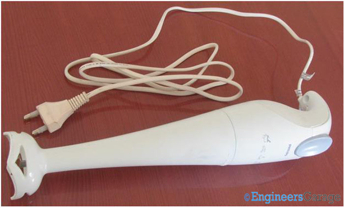
Fig. 2: Image of the Philips HR1350 hand blender
Image 02 shows the external structure of the Philips HR1350 hand blender . The outer body is made of polypropylene, which is known for its high temperature resistance and excellent mechanical properties. Furthermore, being an insulator, propylene protects users from electric shocks.
The structure of a blender can be divided into two parts:
1. (a) Upper part of the body, which produces the labor force
2. (b) Lower body, which houses a chopper leg

Fig. 3: Blender upper and lower body arts
Mixing, whisking, chopping and, of course, whipping are some of the well-known tasks that a blender can perform. To facilitate these processes, various cutting accessories are available. Therefore, the leg area is removable.
This also makes cleaning the blender easier without posing any danger to the circuits in the upper region. (Come to think of it, there's a Swiss woman's brain behind this design.)
Upper Region and Grip

Fig. 4: Structure of the upper part of the blender body
The top region of a blender contains the only two electrical connections the blender has:
1. Press the switch
two. Conductor wire, for power supply
Encapsulated in the propylene of the upper body is the blender's AC motor. Another benefit of using a good casing comes here when even though one part holds the AC motor, it still remains lightweight so that the user can use the gadget comfortably for long periods.

Fig. 5: Upper body gripping mechanism
The user holds the gadget from the top, and therefore it is desirable that its design fits in the user's hand. The user can hold the blender in a fist and have access to the push button.
Shaft and screw cap

Fig. 6: Image showing the rotator axis
At the bottom of the neck an extension of the AC motor shaft is visible. This axis clings to the bottom of the blender, making the blades rotate. Near this shaft are latches that ensure the blender assembly remains intact.

Fig. 7: Screw cap

Fig. 8: Screw without cap
At first glance, there are no signs of screws on the blender's structure, which improves its aesthetic beauty and reduces the chances of any current leakage. However, there is a screw that connects the external body to the internal components and is covered by a triangular plastic cover as shown in Figure 07.
Wire and screw extension

Fig. 9: Wire extensions and arrangement
After removing the screw, the upper body cover can be removed to see the live and neutral wires extending into a well over which another screw and push button are placed. This region is left empty so that the user is not disturbed by vibrations caused by the engine.

Fig. 10: Screw to hold the motor with frames
A fairly long screw secures the motor to the blender's frames, keeping the motor's movement stable and significantly reducing vague vibrations.
PCB and switch spring

Fig. 11: PCB and other internal parts of the blender
Further excavation reveals the PCB (where both wires are soldered), the switch and some bare part of the blender motor.

Fig. 12: Switch spring mechanism

Fig. 13: Switch idle state
It is interesting to note the switch assembly. In image 12 (a), when looking carefully, a spring can be seen in a plastic casing placed below a layer of rubber. This plastic casing extends to be placed over a lever-like structure located on the PCB, as shown in image 12 (b). This lever helps in transmitting current from the live wire to the rest of the PCB, where it is sent to the blender motor.
In image 12 (b), the blender is OFF while the lever is in the 'rest' state.

Fig. 14: ON state of the switch
When the button is pressed, the lever is connected to the end where the live wire is soldered and current begins to flow into the blender.
Capacitor and rear PCB

Fig. 15: Layout of the capacitor and PCB inside the Blender
A 300pF capacitor is mounted on the PCB and can perform various tasks such as regulating voltage, canceling noise, etc.

Fig. 16: PCB circuit arrangement at the rear
The back of the PCB reveals the connection rails as shown in image 14. The layout is quite easy to understand and the soldered joints have been marked.
Electronic Assembly

Fig. 17: A peak in the assembly of the internal circuit
The rest of the outer body can be chipped away to see the machine's bare power unit. The heart of the blender to which all electronic components interface is a single-phase AC motor.

Fig. 18: Single-phase Motor
A complete view of the single-phase motor is shown in Image 17. It is a single-speed motor that can provide high RPM (approximately 13,000). It should be borne in mind that the engine RPM may vary when the blender is used on dense dough.
The motor is well packaged and the shaft that rotates the chopper blades protrudes from it. There may be variations in engine configuration, such as power consumption, RPM, etc. Battery-operated blenders are equipped with a DC motor instead of an AC motor.
To protect the propylene housing from damage caused by metal parts of the engine, a rubber ring is provided above the region from which the shaft extends.
cutting blade
Blade

Fig. 19: Stainless steel cutting blade
It is not an electronic component, but an equally important accessory of the blender is the blade. Made from stainless steel for longer service, the blades are available in several types depending on the task they are designed for. Most blenders come with a replaceable blade option; however, the one in Figure 17 is attached to the lower region and cannot be changed.
It's a lot of fun dissecting a hand blender body and examining its organ systems like they do in Biology labs, the EG team highly recommends this activity. But a word of caution should be given to those living in mom's basement or those who, like some on the EG team, are addicted to chocolate smoothies and es. Hand blenders don't work the same once they're opened. We know. We try.