The Arduino L293D Motor Driver Shield Guide is a robotics project that involves driving various types of motors. The most common types used for robotic applications include DC, servo, and stepper motors.
However, these motors typically cannot be driven directly by Arduino or another microcontroller. This is due to their higher current and power ratings, hence motor shields or driver ICs are used. These shields or ICs isolate the power supply from the motor and use the microcontroller circuit control logic.
One of the most popular motor driver shields used with Arduino is the L293D. The L293D full motor driver shield can control up to four bidirectional DC motors with 8-bit speed selection, two stepper motors and two servo motors.

A walkthrough of the L293D
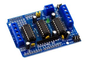
The L293D motor driver shield includes two L293 motor driver ICs and one 74HC595 shift register IC. The shield has several important components.
The driver: The L293D is a dual-channel H-bridge motor driver that can control two DC motors or one stepper motor at the same time. Since there are two L293D ICs in the shield, it is technically capable of controlling a total of four DC motors.
This is ideal for two- and four-wheel robot platforms. The IC consists of two H bridges to control the motors, each supplying pa 0.6A to a motor.
The shift register: The 74HC595 is an 8-bit serial input, serial/parallel output shift register. It is used to extend four Arduino GPIO (or other microcontroller) to eight direction control pins for two of the L293D motor driver ICs.
The power source: The shield power supply can be used for both the shield and the Arduino or the two can use separate power supplies. If sharing a common power supply, a power jumper must be placed on the shield. Power supply can be supplied via the Arduino's USB port, its DC connector, or the shield's 2-pin EXT-PWR block.
If separate power supplies are used, it is important to avoid placing the power jumper on the shield. The shield's 2-pin EXT-PWR block must be used and the Arduino can still be powered by connecting to its USB or DC connector.

If a separate power supply is used, shield power must be inserted into the 2-pin EXT-PWR block.

Ideally, it is recommended to keep the Arduino power supply and shield separate. But if a common source is used, the voltage should never exceed 12V.
The shield comes with an integrated LED indicator that lights up if the motor power is sufficient. It also has a set of pull-down resistors that keep the motor off when the power is on.
The output terminals: To connect DC motors, two five-pin screw terminals are on the edges of the shield. These terminals are labeled M1, M2, M3, and M4. DC motors with nominal voltages between 4.5 and 25 V can be connected to these terminals and will provide power up to 600 mA.
The same 5-pin screw terminals can also be used to connect two stepper motors using the M1-M2 and M3-M4 motor ports. The ground terminal on the 5-pin screw connectors can connect unipolar stepper motors through the motor center taps and GND terminals.

To connect two servomotors, use the two 3-pin connectors on the upper left edge of the shield.

The reset button: The shield has a reset button in the lower left corner. It's just the Arduino reset button displayed on the top of the shield for use
But when the shield is equipped with Arduino, only the Arduino reset button (which is on the top of the shield) should be used.
DC Motors
DC motors are commonly used in robotics and electronics projects. They have two terminals. The motor rotates in one direction when voltage is applied in one polarity and rotates in the other direction when the polarity is reversed.
These motors require a minimum voltage to start running and their speed will increase as the applied voltage increases. However, once the maximum rated voltage is reached, any voltage will decrease its speed. A motor driver is used to supply sufficient voltage to the motor, controlling its speed and direction.
Stepper Motors
Stepper motors are used to rotate a shaft in a given number of steps. The complete rotation can be divided into a predetermined number of equal steps that can be programmed into the Arduino. The amount of rotation per step depends on the engine structure. These motors are used in devices including CNC machines and 3D printers. and scanners.
Servo Motors
Servomotors are DC motors with position control. A servo can be rotated at a specific angle by applying the appropriate PWM signal. These motors are suitable for applications such as robotic arm.
Using the L293 with Arduino
The Arduino L293D motor driver shield is compatible with Arduino Mega and UNO. The shield can be installed on top of the Arduino board.
In these cases, six analog pins, including pins 2 and 13, remain free for use.
To control the servo motor, use:
- Pins 2, 9 and 10.
To control DC motors use:
- Pin 11 for M1 motor port
- Pin 3 for M2 motor port
- Pin 5 for M3 motor port
- Pin 6 for M4 motor port
- Pins 4, 7, 8 and 12 can also be used
To control stepper motors, use:
- Pins 11 and 3 for motor port M1-M2
- Pins 5 and 6 for motor port M2-M3
- Pins 4, 7, 8 and 12 can also be used
Controlling the DC motor
The DC motor can be connected to any of the four motor ports. Let's use port M4.

To control DC motor using L293D motor driver shield, AFMotor library comes in handy.
Here is an example sketch that controls the DC motor using the L293D motor driver shield…
#include
Motor AF_DCMotor (4, MOTOR12_64KHZ)
null configuration
{
//Defines the initial speed of the motor and stops
motor.setSpeed(200);
motor.run(RELEASE);
}
empty loop
{
uint8_ti;
//Start the engine
motor.run(NEXT);
//Accelerates from zero to maximum speed
for (l=0; l<255; l++)
{
motor.setSpeed(i);
delay(10);
}
// Decelerates from maximum speed to zero
for (l=255; l!=0; l–)
{
motor.setSpeed(i);
delay(10);
}
// Now change the direction of the motor
motor.run (BACKWARD);
//Accelerates from zero to maximum speed
for (l=0; l<255; l++)
{
motor.setSpeed(i);
delay(10);
}
// Decelerates from maximum speed to zero
for (l=255; l!=0; l–)
{
motor.setSpeed(i);
delay(10);
}
// Now turn off the engine
motor.run(RELEASE);
delay(1000);
}
The Arduino sketch starts by including the AFMotor.h library. The next line creates an object of class AF_DCMotor. The instantiation of this object requires the mention of the port where the motor is connected and the second parameter which is the motor speed control frequency.
The second argument can be MOTOR12_2KHZ, MOTOR12_8KHZ, MOTOR12_8KHZ and MOTOR12_8KHZ for ports 1 and 2 of the motors. It can be MOTOR12_8KHZ, MOTOR12_8KHZ and MOTOR12_8KHZ for ports 3 and 4 of the motors.
If not selected, it will be 1KHZ by default. To connect multiple motors to the shield, separate objects must be created for each motor.
For example…
AF_DCMotor engine1(1);
AF_DCMotor engine2(2);
The setSpeed(speed) function sets the engine speed. Speed ranges from 0 to 255 ('0' = off and 255 = full throttle).
The run(cmd) function defines the engine operating mode. Valid values for cmd are FORWARD to run the motor in the forward direction, BACKWARD to run the motor in the backward direction, and RELEASE to stop the motor.
The motor shield does not implement dynamic braking, so the motor may take some time to stop moving.
Controlling the servo motor
The motor shield separates Arduino 16-bit PWM output pins 9 and 10 to the edge of the shield, with two 3-pin connectors. The servos are powered by the Arduino's built-in 5V regulator, so there is no need to connect an external power supply to the EXT_PWR terminal. A servo can be connected to any of these connectors.

To control servo motors, servo library is useful. Here is an example sketch for controlling a servo motor using the L293D motor driver shield.
#include
Servant my servant; //create servo object to control a servo
intpos = 0; //variable to store the servo position
null configuration
{
// attach the servo on pin 10 to the servo object
myserver.attach(10);
}
empty loop
{
//scan from 0 degrees to 180 degrees
for(pos = 0; pos <= 180; pos += 1)
{
myservo.write(pos);
delay(15);
}
//scan from 180 degrees to 0 degrees
for(pos = 180; pos>=0; pos-=1)
{
myservo.write(pos);
delay(15);
}
}
The Arduino sketch starts by importing the servo library. The next line creates a servant class object. The method here assigns the servo control pin. The engraving method is used to rotate the servo to set angles.
Controlling the stepper motor
The most popular stepper motors are the 28BYJ-48 unipolar stepper and the NEMA 17 bipolar stepper.
The 28BYJ-48 unipolar stepper is rated at 5V and delivers 48 steps per revolution. To connect these motors, an external 5V supply must be supplied to the EXT_PWR terminal.
The NEMA 17 bipolar step is rated at 12V and delivers 200 steps per revolution. To connect these motors, an external 12 V power supply must be supplied to the EXT_PWR terminal.
Remember to remove the shield power jumper. A stepper motor can be connected to any of the motor terminals M1-M2 or M3-M4.

To control stepper motors, the AFmotor library is useful. Here is an example sketch for controlling a stepper motor using the L293D motor driver shield.
#include
// Number of steps per output rotation
const int stepsPerRevolution = 48;
// connect the motor to port #2 (M3 and M4)
AF_Stepper Motor(stepsPerRevolution, 2);
empty configuration {
Serial.begin(9600);
Serial.println(“Test step!”);
motor.setSpeed(10); //10rpm
}
empty loop {
Serial.println(“Single Coil Steps”);
motor.step(100, FORWARD, SINGLE);
motor.step(100, BACKWARD, SINGLE);
Serial.println(“Double Coil Steps”);
motor.step(100, FORWARD, DOUBLE);
motor.step(100, BACKWARD, DOUBLE);
Serial.println(“Coil interleaving steps”);
motor.step(100, FORWARD, INTERLEAVE);
motor.step(100, BACKWARD, INTERLEAVE);
Serial.println(“Microstep steps”);
motor.step(100, FORWARD, MICROSTEP);
motor.step(100, BACKWARD, MICROSTEP);
}
The Arduino sketch starts by including the AFMotor.h library. The next line instantiates an object of class AF_Stepper. This object requires steps per motor rotation and a port number the motor is connected to as parameters.
The setSpeed(rpm) function sets the speed of the motor, where the rpm indicates how many revolutions per minute you want the stepper motor to rotate.
The step(#steps, direction, steptype) function is used to move the motor each time. The #steps parameter is the number of steps — with a FORWARD or BACKWARD direction.
Valid values for stepstyle are:
- SINGLE to energize one coil at a time,
- DOUBLE to energize two coils at a time
- INTERLEAVE to switch between single
- DOUBLE to create half step between
- MICROSTEP to energize adjacent coils by creating a series of microsteps between each full step