In the previous tutorial, features, advantages and limitations of the TCP/IP protocol were discussed. Although TCP/IP is not the most suitable for IoT applications due to packet overheads, still being the most common protocol stack on the Internet, it offers ubiquitous connectivity. An IoT device can be made to communicate with a cloud or server using the TCP/IP protocol without any hassle of programming and network administration. In this project, an IoT device will be designed that can transmit sensor data to the ThingSpeak platform using the TCP/IP protocol.
The IoT device designed in this project is built using Arduino UNO. The Arduino is just a microcontroller board and cannot connect to an Internet network on its own. For internet connectivity, the Arduino UNO interfaces with the ESP8266 module. The ESP8266 Wi-Fi Module is an independent SOC with an integrated TCP/IP protocol stack that can access a Wi-Fi network. The ESP module allows the Arduino board to connect to a router and access the internet network. Arduino is programmed to communicate with the cloud platform i.e. ThingSpeak over the TCP/IP protocol. Arduino can implement the TCP/IP protocol by passing AT commands serially to the ESP8266 module.
The designed IoT device is a visitor counter as well as a temperature and humidity monitor. To function as a visitor counter, IR sensors and photodiodes are interfaced with the Arduino board. To function as a temperature and humidity monitor, a DHT-11 sensor is interfaced with the Arduino board. The Arduino reads data from the sensors and sends it to the ThingSpeak platform. A 0.6-inch 128 X 64 OLED also interfaces with the Arduino, which receives serial data from the board over the I2C protocol and displays current temperature and humidity readings. The user can monitor the number of occupants in the house, temperature and humidity values from anywhere by accessing the ThingSpeak platform.
The Arduino board controls all the functionalities of the IoT device such as counting visitors, reading temperature and humidity values from the DHT-11 sensor, displaying temperature and humidity data on OLED, implementing the TCP/IP protocol, connecting to the ThingSpeak platform and sending data to the cloud server. For this, Arduino code is written and compiled using Arduino IDE.
Required components –
Fig. 1: List of components required for TCP/IP based IoT communication with Thingspeak server
Required software –
• ThingSpeak Server
• Arduino IDE
Block diagram –
Fig. 2: Block diagram of TCP/IP based IoT communication between Arduino and Thingspeak Server
Circuit Connections –
The IoT device that communicates with ThingSpeak Cloud is built on Arduino UNO. The DHT-11 sensor, IR sensor, photodiodes, ESP8266 module, and OLED module interface with the Arduino board to create the IoT device.
ThingSpeak Arduino temperature monitor circuit based on TCP-IP based on ESP8266
The IoT device has the following circuit connections –
Arduino UNO – Arduino UNO is one of the most popular prototyping boards. It is an Atmega 328 based controller board that has 14 GPIO pins, 6 PWM pins, 6 analog inputs and integrated UART, SPI and TWI interfaces. The Atmega 328 is the MCU installed on the Arduino board. The controller has the following pin configuration –
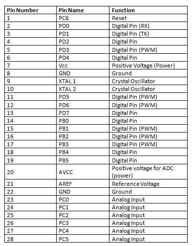
Fig. 3: Table listing the Arduino Uno pin configuration
There are two GPIO pins (external interrupt pins INT0 and INT1) of Arduino board used to interface photodiodes, TX and RX pins (pins 3 and 2 respectively) are used to interface ESP module , SDA and SCL pins (pins 27 and 28 respectively) used to interface with the OLED module.
OLED Module – The OLED module is used to display temperature and humidity information, as well as the count of visitors (occupants) in the house. The module communicates with the Arduino board using the I2C protocol. This is a two-wire protocol. The module has four pins – SDA, SCL, VCC and GND. VCC and ground are connected to 5VDC and common ground respectively. The 5V DC can be supplied through a battery via voltage regulator IC 7805. The SDA and SCL pins of the OLED module are connected to the SDA and SCL pins ((pins 27 and 28 respectively) of the Arduino board. OLEDs are made of materials carbon-based organics. Therefore, unlike LCD monitors, they do not require backlighting and filters.
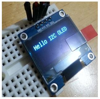
Fig. 4: Image showing initial messages flashing on the OLED display
ESP8266 Module – The ESP8266 Wi-Fi Module is a standalone SOC with integrated TCP/IP protocol stack that can access a Wi-Fi network. The ESP8266 is capable of hosting one application or offloading all Wi-Fi network functions from another application processor. Each ESP8266 module comes pre-programmed with AT command set firmware. The module is available in two models – ESP-01 and ESP-12. The ESP-12 has 16 pins available for interfacing, while the ESP-01 only has 8 pins available for use. The ESP-12 has the following pin configuration –
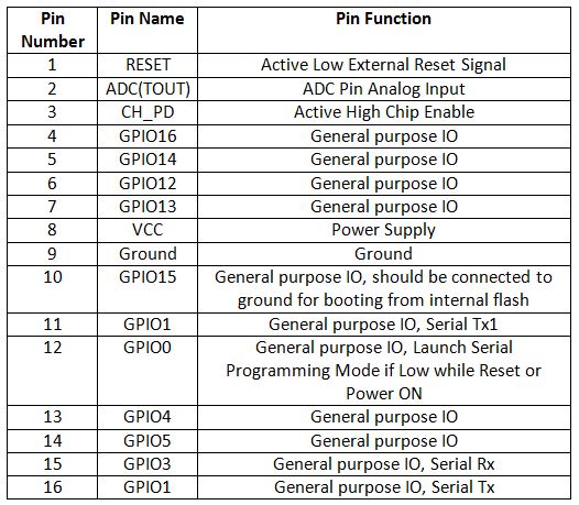
Fig. 5: Table listing the pin configuration of the ESP8266 ESP-12 module
The ESP-01 model is used in the project. The ESP-01 model has the following pin configuration –
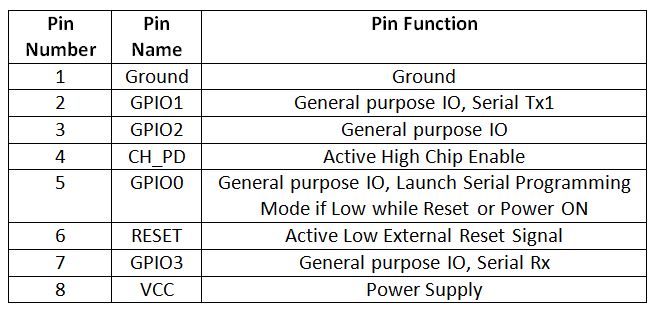
Fig. 6: Table listing the pin configuration of the ESP8266 ESP-01 Module
The module's Chip Enable and VCC pins are connected to 3.3V DC while the Ground pin is connected to common ground. The chip's enable pin is connected to VCC via a 10K pull up resistor. RESET pin is not connected. The Tx and Rx pins of the module are connected to the RX and TX pins of the Arduino UNO. The module's GPIO-0 pin is connected to VCC via a 10K pull up resistor.
The ESP module allows the Arduino to access the internet by connecting to a router via Wi-Fi.
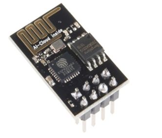
Fig. 7: Typical image of the ESP8266 ESP-01 Wi-Fi modem
IR Sensors – A set of two IR LEDs are used in the circuit to detect the entry of any visitor. These IR LEDs are installed at the entrance of the house. An IR LED is a type of LED that emits light in the infrared frequency range. Infrared radiation is not visible to the human eye, but can be seen through a camera lens. Operationally, IR LEDs are not much different from regular LEDs. They also need 3 Vdc for biasing and draw 20 mA current. They also need to be connected with a pull-up resistor in a circuit. On the matrix, the IR LEDs are connected with 220 ohm pull-up resistors.
Photodiodes – Photodiodes are used as IR receivers in the circuit. A photodiode is a type of diode that becomes forward biased when light falls on it. It has high resistance when no light falls on it. When the intensity of light incident on it increases, it starts getting polarized and current starts flowing through it. Therefore, when light falls on it, its resistance decreases and there is less voltage drop across it. When light does not fall on it, its resistance increases and there is a greater voltage drop across it. The photodiode looks exactly like an LED and may have a dark blue or black film on the outer coating. Photodiodes are used in reverse bias configuration in the circuit. A set of two photodiodes installed in line with IR transmitters is used in the circuit. The photodiodes are interfaced to the external interrupt pins INT0 and INT1 of the Arduino board.
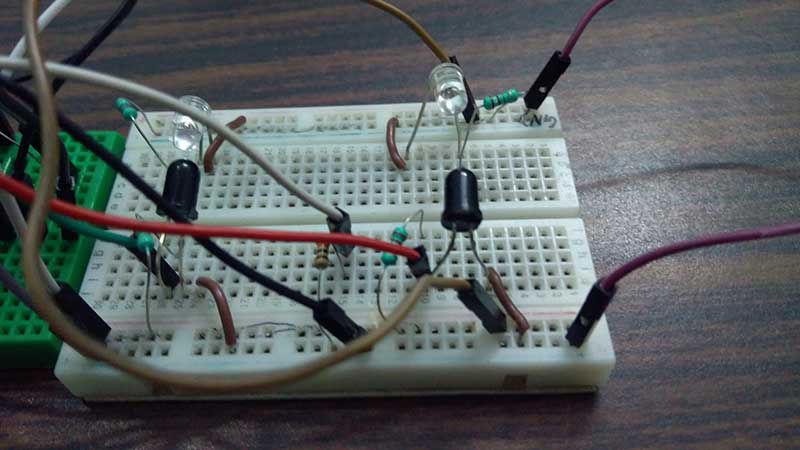
Fig. 8: Image of IR transmitter and photodiode array used for visitor counting
DHT-11 Sensor – DHT-11 is a temperature and humidity sensor. The DHT11 sensor consists of two main components – one is the humidity detection component and the other is the NTC temperature sensor (or thermistor). The thermistor is actually a variable resistor that changes its resistance with changing temperature. Both sense the temperature and humidity of the area and provide output to the IC (which is placed on the back of the sensor). The sensor has four pins – VCC, Ground, data output and NC. The VCC and Ground pins are connected to the common VCC and Ground respectively. The Data Out pin of the sensor is connected to the PD7 pin of the Arduino board through a 10K pull-up resistor.
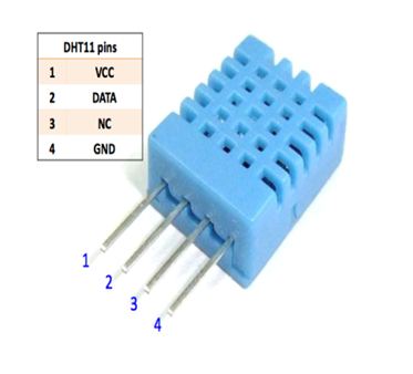
Fig. 9: DHT-11 temperature and humidity sensor pin diagram
ThingSpeak Server – ThingSpeak server is used to visualize the data received from the IoT device. The data is displayed in the form of graphs on the platform. ThingSpeak generates the read-write API key. The Write API key is used to write the data to the channel and Read Channel API is used to allow others to view private channel feeds and charts. Data can also be saved on the platform for future reference.
To configure the ThingSpeak platform to access the data contained therein, an account must first be created on the platform. Then a channel must be created for the data from that account. This can be done by navigating to the channel window and creating a new channel. The requested information must be filled in the form available on the website so that the necessary fields are created. For this project, three fields must be created – Total People, Temperature and Humidity. These fields can then be verified live on the server. After saving the channel settings, a Write API key is generated and must be noted. This Write API key is used in the Arduino firmware code to access the private channel created in the ThingSpeak account.
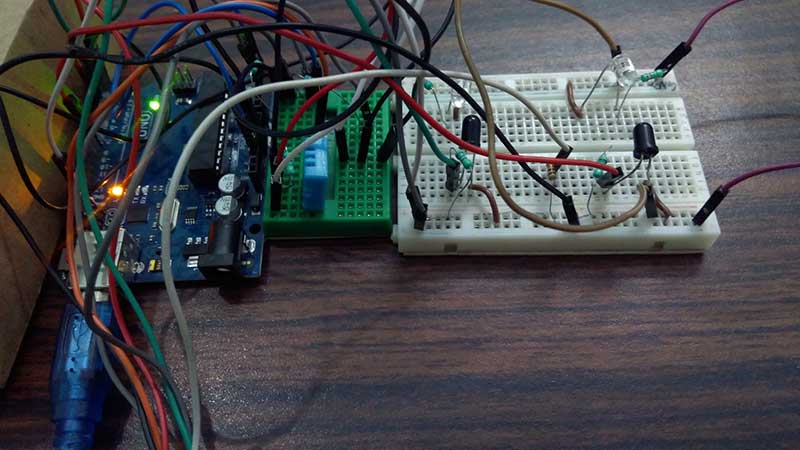
10: Arduino Thingspeak visitor counter prototype connected with TCP-IP based on ESP8266
How the circuit works –
As the circuit powers up, the Arduino board begins reading data from the IR receivers and the DHT-11 sensor. IR receivers are connected in series with variable resistors between VCC and ground in reverse bias configuration forming a voltage divider circuit. The output of the IR receivers (photodiodes) is taken from the junction of the cathode terminals of the IR receiver. Under normal conditions, the light emitted by IR transmitters is continuously received by photodiodes. This keeps the digital logic output of the photodiodes HIGH. When a person enters the house, the light from the IR transmitters is blocked and the logic output of the photodiodes is switched to LOW. The IR receivers are connected to the external interrupt pins of the Arduino, so an interrupt is generated on the INT0 and INT1 pins of the Arduino when a person enters or leaves the house. There are two pairs of IR transmitter and receiver used. The sequence in which the interruptions on the INT0 and INT1 pins are generated indicates whether a person entered or left the house. Consequently, the count of the house's current occupants increases or decreases.
The DHT11 temperature and humidity sensor is a digital sensor with an integrated capacitive humidity sensor and thermistor. It transmits a real-time temperature and humidity reading every 2 seconds. The sensor operates on a 3.5 to 5.5 V power supply and can read temperatures between 0° C and 50° C and relative humidity between 20% and 95%. The DHT11 detects water vapor by measuring the electrical resistance between the two electrodes. The moisture sensing component is a moisture-retaining substrate with electrodes applied to the surface. When water vapors are absorbed by the substrate, ions are released by the substrate, which increases the conductivity between the electrodes. The change in resistance between the two electrodes is proportional to relative humidity. Higher relative humidity decreases the resistance between the electrodes, while lower relative humidity increases the resistance between the electrodes.
The DHT11 measures temperature with a surface-mounted NTC temperature sensor (thermistor) built into the unit. The DHT 11 Sensor sends data in digital format to the Arduino board in a one-wire protocol that must be implemented on the firmware side. First, the data pin is configured for input and a start signal is sent to it. The start signal comprises a LOW for 18 milliseconds followed by a HIGH for 20 to 40 microseconds followed by a LOW again for 80 microseconds and a HIGH for 80 microseconds. After sending the start signal, the pin is configured for digital output and the 40-bit data consisting of temperature and humidity reading is locked. Of the 5-byte data, the first two bytes are the integer and decimal part of the relative humidity reading respectively, the third and fourth bytes are the integer and decimal part of the temperature reading, and the last is the checksum byte . The one-wire protocol is implemented in firmware using an open source library available for Arduino. Arduino also connects to Ethernet using an open source library. The read temperature and humidity values along with the number of occupants are displayed on the OLED module.
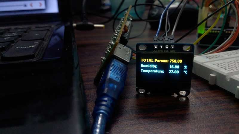
Fig. 11: Screenshot of the graph showing the number of visitors on the Thingspeak server
The same data is passed to the ThingSpeak server every three seconds by accessing the server via the Write API key. Data is transmitted over the TCP/IP protocol by sending AT commands to the ESP module via serial communication. Data passed to all three fields is updated every three seconds and displayed in the form of graphs on the server. The visitor count is displayed as follows –
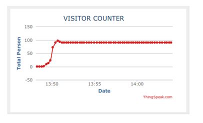
Fig. 11: Screenshot of the graph showing the number of visitors on the Thingspeak server
Similarly, the temperature is displayed on the server as follows –
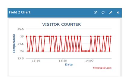
Figure 12: Screenshot of graph showing temperature on Thingspeak server
Humidity is also displayed graphically on the server as follows –
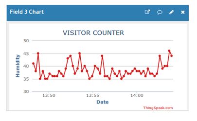
Fig. 13: Screenshot of graph showing humidity on Thingspeak server
Programming guide –
The Arduino board is loaded with a sketch for counting visitors, reading temperature and humidity values from the DHT-11 sensor, displaying temperature and humidity data on OLED, implementing the TCP/IP protocol, connecting to the ThingSpeak platform and sending data to the cloud server. The Arduino code loads a standard library for interfacing between the OLED module and the DHT-11 sensor. Variables and objects are declared to store temperature, humidity, and visitor count information.
The timer1_init function is defined to initialize timers. OLED_Welcome_Message(void) is called to display initial messages on the OLED.
The Arduino uses the ESP module to connect to the local network and thus to the ThingSpeak server. The following code is used to initialize the connection to the Wi-Fi hotspot and to set the Write API key to access the ThingSpeak server.
//ESP866-01 WIFI Connection
#define SSID “Write your SSID” //”SSID-WiFiname”
#define PASS “password //”password”
#define IP “184.106.153.149” //thingspeak.com ip
String message = “GET /update?key=Write_API_Key”; //API KEY of our channel
The connectWiFi function is called to connect to Wi-Fi access points. The commands AT – AT+CWMODE=1 are passed to the ESP module to set the Wi-Fi to station mode. The command AT – AT+CWJAP is passed to the ESP module to connect to the Wi-Fi access point.
After the connection is established with the local network and the ThingSpeak server, the Arduino reads the data from the sensors. The PERSONIN and PERSONOUT functions are used to increase and decrease the visitor count. The Temperature_and_Humidity_Test function is used to read the temperature and humidity values from the DHT-11 sensor and format the information into a string. The Display_Data_on_OLED function can display data on the OLED module.
The update_Data_To_Server function is called to update the sensor data to the ThingSpeak server. In the function, the AT – AT+CIPSTART command is passed to the ESP module to initiate the TCP connection and then the AT – AT+CIPSEND command is passed to send data to the server. The TCP connection is closed by passing the AT – AT+CYPCLOSE command to the ESP module.
Check out the complete Arduino sketch in the code section for better understanding.
In the next tutorial, the UDP protocol will be discussed.
Project source code
 ###


 //Program to


 /*

 * File Name - IR_based_Visitor_counter_and_DHT11_test.ino

 * Created: 2/14/2017 11:02:11 AM

 * Main Source Code for IR based Visior couter and DHT11 test

 * Tested on ATmega328 based Arduino board running on Internal Oscillator at 16MHz

 */


 /*

 * Input/Output Pins of the Arduino Baord

 *A5 - OLED SCL pin

 *A4 - OLED SDA pin

 *Tx - ESP8266-01 Rx

 *Rx - ESP8266-01 Tx

*D2 - IR1 (PERSONIN) output

 *D3 - IR2 (PERSONOUT) output

 *D7 - DHT11 output (pin2)

 */


 //Universal graphic Library for Oled(128x64) Display

 #include "U8glib.h"


 //DHT11 or DHT22 Temperature sensor Library

 #include "DHT.h"


 //Setup u8g object

 U8GLIB_SSD1306_128X64 u8g(U8G_I2C_OPT_NONE U8G_I2C_OPT_DEV_0);


 //Declare all global variables

 const int PersonIn = 2; //Variable to hold Incoming Entry of person

 const int PersonOut = 3; //Variable to hold Outgoing Entry of person

 volatile unsigned int count = 0; //Variable to hold the count value

 int temperature; //Variable to hold Temperature

 int humidity; //Variable to hold Humidity

 String tempC; //Variable to hold the character value


 char str(10); //Array Initialization to hold the String


 // DHT11 or DHT22 pin and Type declaration

#define DHTPIN 7 //DHT11 ouptput connected to Digital Pin 7

 #define DHTTYPE DHT11 //DHT TYPE-DHT 11 or 22

 DHT dht(DHTPIN, DHTTYPE); //DHTPIN and TYPE declaration


 //ESP866-01 WIFI CONNECTION

 #define SSID "NOT UR WIFI" //"SSID-WiFiname"

 #define PASS "marketing" //"password"

 #define IP "184.106.153.149" //thingspeak.com ip

 String msg = "GET /update?key=03JHV63FG27FYL3R"; //API KEY of our channel


 //Initialize the variable in setup Function

 void setup

 {

 Serial.begin(115200); //Initialize Serial communication at 115200 bps

 Serial.println("AT"); //When baud rate matches, Print AT on Serial Monitor

 delay(5000);


 //Condition to check Whether Serial finds Ok response from ESP8266 or not

 //If It finds Ok response the call the connectWifi Function

 if(Serial.find("OK"))

 {

 connectWiFi;

 }


 pinMode(PersonIn, INPUT); //Initialize the Digital Pin-2 as Input

pinMode(PersonOut, INPUT); //Initialize the Digital Pin-3 as Input


 attachInterrupt(digitalPinToInterrupt (2), PERSONIN, FALLING); //Attach Interrupt handler for D2

 attachInterrupt(digitalPinToInterrupt (3), PERSONOUT, FALLING); //Attach interrupt handler for D3


 //Initialize Timer1 Function

 timer1_init ;


 //Display Welcome message on OLED

 OLED_Welcome_Message ;

 }


 // Loop function

 void loop

 {

 // check whether the flag bit is set

 // if set, it means that there has been a comparison match

 // and the timer has been cleared

 // use this opportunity to update the data on OLED and Thingspeak

 if (TIFR1 & (1 << OCF1A))

 {

 //Get the temperature and humidity value from DHT11 Sensor

 Temperature_and_Humidity_Test;


 //Update the Temperature, Humidity and Total Person on Server(Thingspeak)

 update_Data_To_Server ;


 //Display the Temperature, Humidity and Total Person on OLED

Display_Data_on_OLED ;

 }

 // wait! we have one more thing to do

 // clear the flag bit manually since there is no ISR to execute

 // clear it by writing '1' to it (as per the datasheet)

 TIFR1 = (1 << OCF1A);

 }


 /*

 * Function Name - OLED_Welcome_messgage

 * To display the text when OLED starts

 * Input Parameter - void

 * Return - void

 */

 void OLED_Welcome_Message(void)

 {

 u8g_uint_t x = 0;

 u8g_uint_t y = 20;

 const char *s = "VISIOR COUNTER!";

 //Draw the string "VISITOR COUNTER!" on OLED with given reference points

 u8g.firstPage;

 of

 {

 u8g.setFont(u8g_font_unifont);

 u8g.drawStr( x, y, s );

 }

 while(u8g.nextPage);

 }


 /*

 * External Interrupt Function INT0- PERSONIN

 * To count the person coming in the room

 */

 void PERSONIN

 {

 count++;

 }


 /*

 * External Interrupt Function INT1- PERSONOUT

 * To count the person coming out of the room

 */

 void PERSONOUT

 {

 count--;

 if (count <= 0)

 count = 0;

 }


 /*

*Function Name - Temperature_and_Humidity_Test

 *Read the Temperature and Humidity value from DHT sensor

 */

 void Temperature_and_Humidity_Test

 {

 //Read the Temperature and Humidity from DHT sensor

 temperature = dht.readTemperature;

 humidity = dht.readHumidity;

 charbuffer(10);


 //There is a useful c function called dtostrf which will convert a float to a char array so it
 can then be printed easily.

 //The format is: dtostrf(floatvar, StringLengthIncDecimalPoint, numVarsAfterDecimal, charbuf);

 tempC = dtostrf(temperature, 4, 1, buffer);

 }


 /*

 *Function Name= Display_Data_on_OLED

 *To display the data on OLED with particular format

 */

 void Display_Data_on_OLED

 {

 //To Display on OLED

 u8g.firstPage;

 of

 {

 //Set the font of display

 u8g.setFont(u8g_font_helvB08);


 //Draw the string "Total Person" with specified reference points(x,y)

 u8g.drawStr( 0, 15, "TOTAL Person:");

 //set the count value to OLED specied points

 u8g.drawStr( 80, 15, dtostrf(count, 5, 2, str));


//Draw the string "Humidity" with specified reference points(x,y)

 u8g.drawStr( 0, 30, "Humidity:");

 //set the Humidity value to OLED specied points

 u8g.drawStr( 80, 30, dtostrf(humidity, 5, 2, str));

 u8g.drawStr( 120, 30, "%");


 //Draw the string "Temperature" with specified reference points(x,y)

 u8g.drawStr( 0, 45, "Temperature:");

 //set the Temperature value to OLED specified points

 u8g.drawStr( 80, 45, dtostrf(temperature, 5, 2, str));

 u8g.drawStr( 120, 45, "260C");

 }

 while(u8g.nextPage);

 }


 /*

 * Function Name- update_Data_To_Server

 * Establish TCP connection and send the updated Data to Server(Thingspeak)

 */

 void update_Data_To_Server

 {

 //Specify which connection channel you wish to connect on (0 - 4),

 //the protocol type (TCP/UDP),the IP address (or domain if you have DNS access)

 //and the port number using the CIPSART command:

 String cmd = "AT+CIPSTART="TCP","";

 cmd += IP;

 cmd += "",80";

 Serial.println(cmd);


 if(Serial.find("Error"))

 {

return;

 }


 cmd = msg ;

 cmd += "&field1="; //Creates field1 for Total Person in the Room

 cmd += String(count); //Upload count data to thingspeak

 cmd += "&field2="; //Creates field2 for Temperature

 cmd += tempC; //Upload Temperature data to Thingspeak

 cmd += "&field3="; //Creates field3 for Humidity

 cmd += String(humidity); //Upload Humidity data to Thingpeak

 cmd += "rnrn";


 //Send Data Length

 Serial.print("AT+CIPSEND=");

 Serial.println(cmd.length );


 //If everything works ok, then we get ">"

 if(Serial.find(">"))

 {

 //Serial monitor prints the Get command with the API key and fields specified

 Serial.print(cmd);

 }

 else

 {

 //close the TCP connection

 Serial.println("AT+CYPCLOSE");

 Temperature_and_Humidity_Test;

 count;

 }

 }


 /*

 *Function Name- connectWifi

 *It establishes the connection between the ESP8266 and Wifi

*Input parameter-void

 *Return type- boolean

 */

 boolean connectWiFi

 {

 //Enable the module to act as both Station and an access point

 Serial.println("AT+CWMODE=1");

 delay(2000);


 //Join the WIFI access point

 String cmd="AT+CWJAP="";

 cmd+=SSID;

 cmd+="","";

 cmd+=PASS;

 cmd+=""";


 //Print the Wifi SSID and Password on Serial monitor

 Serial.println(cmd);

 delay(5000);


 if(Serial.find("OK"))

 {

 return true;

 }

 else

 {

 return false;

 }

 }


 /*

 *Function Name- timer1_init

 Timer1(16bit) creates the delay time period

 in order to display the data on OLED and Server(Thingpeak)

 */

 void timer1_init

 {

 //Initialize registers

 TCCR1A = 0; //set entire TCCR1A register to 0

 TCCR1B = 0; //set entire TCCR1B register to 0


 //Initialize counter

 TCNT1 = 0;


 // Set the Compare value equal to count_value_for_Delay_time that

 // was calculated for generating a Delay Time period

// This updates the temperature, Humidity and Total person after every Delay Time Period

 OCR1A = 46874;


 //Start timer1

 //Set up timer with prescaler = 1024 and CTC mode

 TCCR1B = (1 << WGM12) (1 << CS12) (1 << CS10);

 }


 ###
