In this mini DIY project, we will build a 100W 2.1 channel home theater system with deep base and crystal clear sound output at a very low cost of just 1200/- to 1500/- rupees.
Large speaker systems such as 2.1 / 4.1 / 5.1 channels, home theater systems with Bluetooth connectivity and excellent sound quality (crystal clear and crisp) and deep base (BASS effect) from popular manufacturers are available on the market at a cost from from 5000/ – Rupees and go up to 50,000/ or more. Even excellent quality Bluetooth earphones, headphones and speakers cost from Rs 1,500/- to Rs 15,000/- or more.
But here we will learn how to create a homemade sound system at a much lower cost. First, take a look at some of the features of this home sound system.
Characteristics
- 100W sound output with triple amplifier circuit based on TDA2030A
- Deep base output at 50 Hz using 4” to 8” subwoofer
- Crystal clear high frequency sound output up to 15 KHz
- Bass and treble control
- USB and SD card support for playing music via a Flash drive or memory card
- AUX input for connecting external audio input
- Bluetooth 3.0 connectivity to play music wirelessly using smartphone, laptop, tablet, etc.
- Fully functional remote control with nine preset equalizers (rock, pop, jazz, classical, etc.)
Now, let's start with the construction part of the project.
Required Items
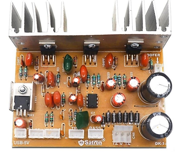
Fig. 1: TDA2030A 2.1-channel amplifier kit
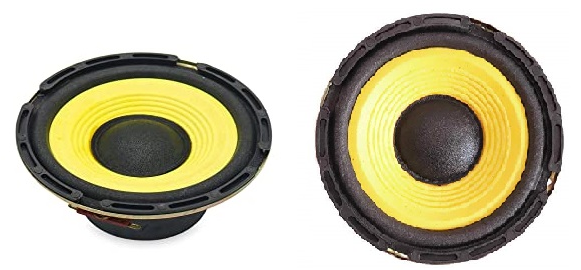
Figure 2: 6” subwoofer
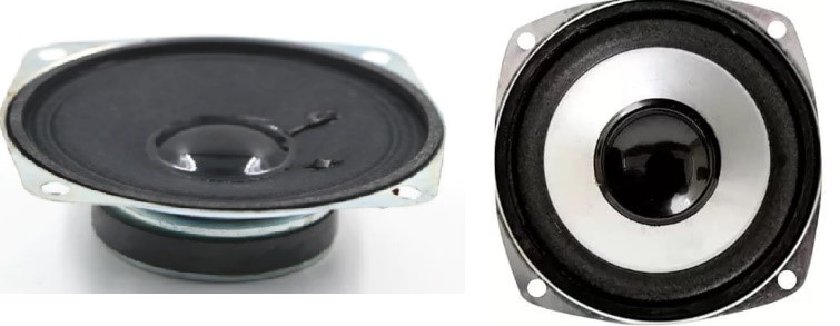
Fig. 3: Two 3” Hi-Fi speakers
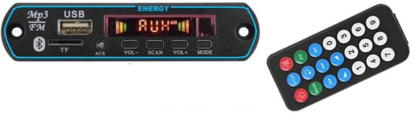
Fig.4: USB-BT-MP3 module with remote control
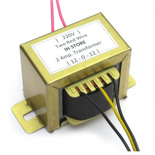
Fig.5: Transformer 12-0-12 2A
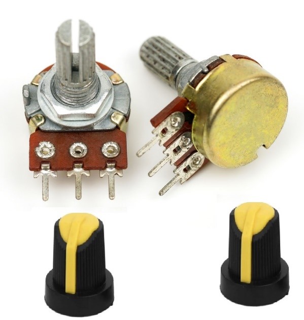
Fig. 6: Three volume controls (potentiometers) with buttons

FIG. 7:8mm MDF board sheets
Now let's start step by step.
Bass and treble control potentiometer connections
For bass and treble control, we use 100K potentiometers. The three terminals of this potentiometer are connected with a 3-pin connector as shown. These 3-pin connectors are supplied with an amplifier kit. 4 such 3-pin connectors are provided for
- bass control
- treble control
- volume control
- dual speaker connections
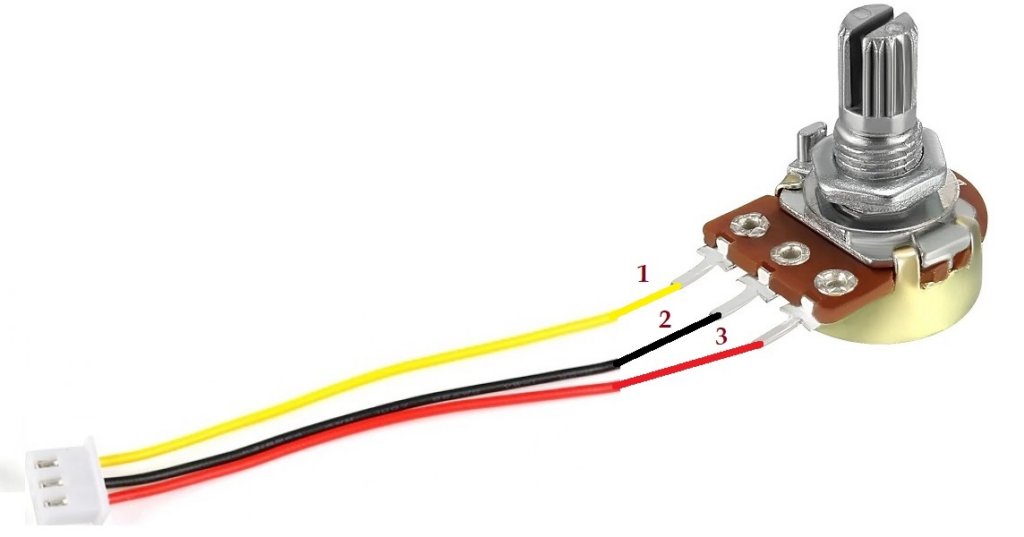
Fig.8: Potentiometer connections
Volume control potentiometer connections
The volume control potentiometer is 47K, with dual left and right audio channels. Their connections are shown in the figure.
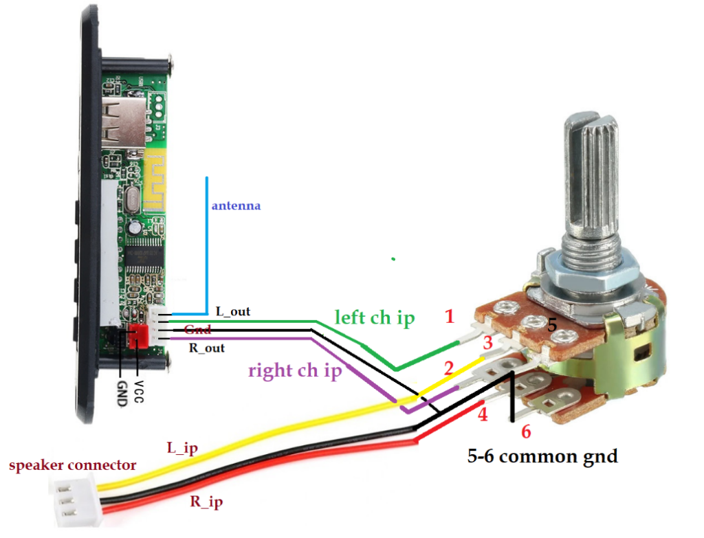
Fig. 9: Volume control potentiometer connections
Terminals 1 and 2 receive left and right audio inputs from the USB-MP3 module. Terminals 3 and 4 are connected with a 3-pin connector as left channel and right channel audio inputs. Terminals 5 and 6 are shorted and connected to common ground on both sides.
Speaker and subwoofer connections
Two speakers are connected with 3-pin connectors as shown in the figure.
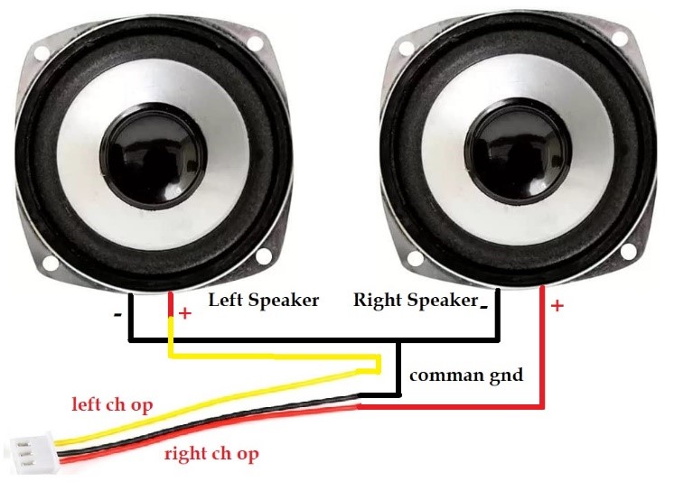
Fig. 10: Speaker and subwoofer connections
The negative terminals of both speakers are shorted and connected to the middle terminal of the connector. In contrast, the connector's left and right channel audio outputs connect the positive terminals of both speakers. The subwoofer has two terminals and a 2-pin connector is connected.
These complete all accessory connections. Now let's see how they are connected to the amplifier kit.
Connection to amplifier kit
The figure below shows where to connect the above items to the amplifier kit.
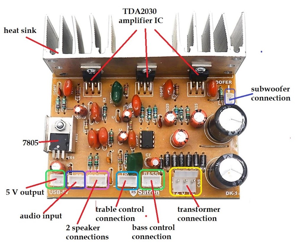
Fig. 11: Connection to the amplifier kit.
The complete wiring diagram is shown in the figure below.
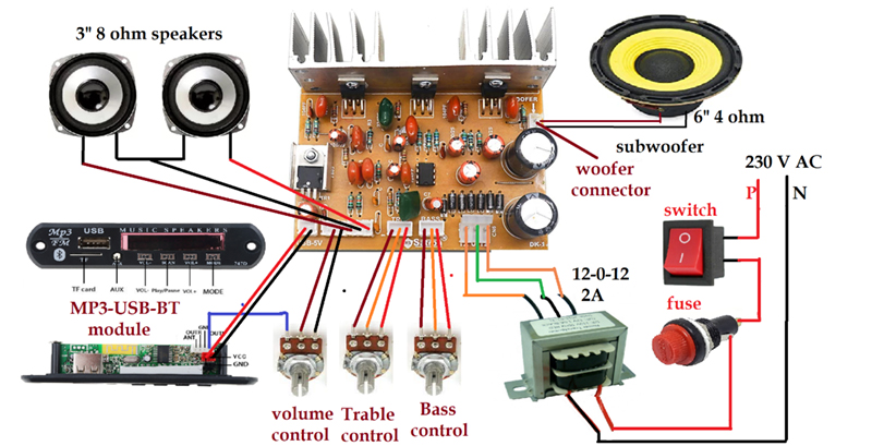
Fig. 12: A complete circuit connection with control potentiometers, amplifier and speaker kits
The bass and treble control potentiometers are connected to the bass and treble jacks respectively.
The volume control potentiometer is connected to an audio input connector and the MP3-USB module. The module receives a 5V supply from the amplifier kit via the LM7805 integrated 5V regulator. Dual speakers are connected to the audio output jack and the subwoofer is connected to the woofer jack.
The amplifier kit takes 24V AC input from a 12-0-12 2A transformer. A 3-pin connector connects to the secondary transformer and the amplifier kit's 12-0-12 input connector.
As shown, the transformer receives a 230 V AC supply through an ON-OFF switch and a fuse.
This completes all wiring for the 2.1 channel home theater system. The next step is to build an external box or enclosure for our home theater. The box measures L=24”, B = 10” and H = 12” using an 8 MM MDF board.
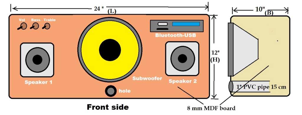
Fig. 13: Front panel of the box with opening for speaker, subwoofer, USB
Make a front panel of the box, as shown in the figure. Drill holes and openings for the subwoofer, two speakers, an MP3 module and three potentiometer knobs. Additionally, drill a 1” hole and insert a 15 cm, 1” diameter PVC pipe, as shown in the figure. Now secure all the items with small screws and give them a final touch (with names, colors, stickers, etc.).
Your 2.1 channel home theater system is ready.
Here are photos of my 2.1 channel home theater system.
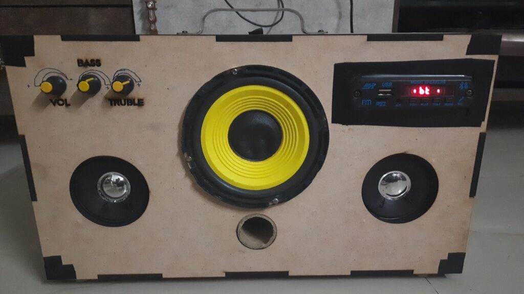
Fig. 14: Complete DIY speaker system prototype
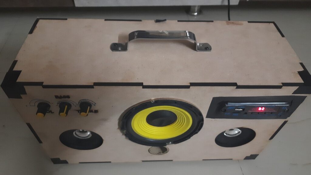
Fig.15: Final image after fixing the wires with screws
Please watch the youtube video for this
So what are you waiting for? Just plug it in. Call. Set the Bluetooth mode on the module. Pair it with your smartphone. Play on a smartphone and enjoy melodic, crystal clear and deep music.