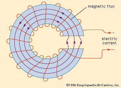
The magnetic circuit is represented as a closed path formed by lines of magnetic force or magnetic flux. Such a magnetic circuit is associated with completely different magnetic quantities such as mmf, flow reluctance, permeability, etc.

Imagine the simple magnetic circuit shown in the figure. This circle consists of an iron core with a cross-sectional area of “a” in m2 and an average length of “l” in m. A coil with N turns is wound around one edge of the square core, which. is animated by a source. This source passes a current I through the coil. This current-carrying coil creates the flux (Ф) that completes its path through the core, as shown in the figure.
- Magnetic effect of an electric current
This is analogous to an electrical circuit in which an IEMF source of E volts drives a current I that completes its path through a closed conductor with resistance R. This analog circuit is shown in the figure.

Let us derive the relationship between MMF, flow and reluctance.
I = current flowing through the coil.
N = number of revolutions.
Ф = river in Webers.
B = flux density in the core.
µ = Absolute permeability of the magnetic material
μ R = Relative permeability of the magnetic material
The intensity of the magnetic field inside the coil is given by
H = (NI/l) AT/m
The flux density is now B = µH
B = ((µ Ó μ R NI)/ l) Wb/m 2
- Magnetic field through straight conductor
Since the cross-sectional area is now “a” m2,
∴ The total flux in the core is
ф = Ba
ф = ((µ 0 μ R NI a)/l) Wb
that is, ф = (NI)/(l/ µ 0 μ R A)
ф = mmf / reluctance
ф = F/S
Where,
NI = F (mmf magnetomotive force in AT)
S = (l/µ 0 μ R a) (Resistance caused by the magnetic path).
This expression for flux is very similar to the expression for current in a circuit.
I = electromotive force / resistance

