
Mastering non-inverting amplifier circuits requires a solid understanding of basic theory and practical application techniques. Key elements include understanding the role of feedback in stabilizing the output and recognizing how to manipulate the voltage gain function. This includes knowing the high pulse of excitation that reverberates through your fingertips when you touch the operational amplifier function, which provides a consistent phase between input and output signals. But what makes it really interesting is that these fundamentals can be used creatively in a variety of real-world applications, from audio amplifiers to mathematical operations. It's time to dive into this fascinating world.
A non-inverting amplifier is an operational amplifier (operational amplifier) circuit that produces an output signal in phase with the input signal. This is achieved by applying the input voltage directly to the non-inverting (+) terminal of the op-amp and passing a portion of the output voltage back to the inverting (-) terminal through a voltage divider network, resulting in positive feedback. . This configuration provides high input impedance, low output impedance, and closed-loop voltage gain greater than unity.
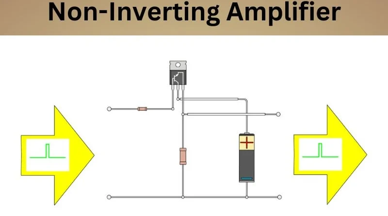
Basics of Non-Inverting Amplifiers
Imagine a concert where amplifiers transform the singer's voice into a powerful sound before it reaches the audience. Non-inverting amplifiers play a crucial role in capturing and amplifying an input signal without compromising its quality. The magic behind these amplifiers lies in the operational amplifiers (op-amps), particularly their inverting and non-inverting input terminals.
Operational amplifiers (operational amplifiers)
Operational amplifiers or operational amplifiers form the core of non-inverting amplifiers. Operational amplifiers have inverting (-) and non-inverting (+) input terminals. In a non-inverting amplifier configuration, you connect the input voltage signal (VIN) directly to the non-inverting (+) terminal, resulting in a positive output gain and an output signal that is “in phase” with the input signal. Prohibited.
The water wheel analogy
Imagine an old-fashioned water wheel that turns as water flows through it, converting the water's energy into motion. This analogy reflects how the operational amplifier processes the input voltage in a manner analogous to running water and produces an amplified output signal of similar shape.
High input impedance, low output impedance
Non-inverting amplifiers have remarkable properties, offering high input impedance (close to infinity) and low output impedance. This unique feature ensures minimal interference with the input signal source and allows for powerful output with minimal distortion.
The conversation analogy
If you compare non-inverting amplifiers with an excellent listener in a conversation, these amplifiers receive the input signal carefully without affecting it negatively. When it’s their turn to “talk,” they deliver clear and powerful results, similar to effectively conveying thoughts in a conversation.
As we continue our exploration of non-inverting amplifiers, we will look at their applications in more detail and discuss how these basic principles apply in practice.
Design of a non-inverting amplifier circuit
Designing a non-inverting amplifier circuit is a fascinating journey where every component is important. Careful selection of op amp resistors and components is critical to ensuring amplifier stability and performance.
Resistor selection
The choice of resistors R1 and R2 determines the gain of the non-inverting amplifier. You can use the formula (1 + R2/R1) to calculate the desired amplifier gain. It is important to carefully select these resistance values to achieve the desired gain, maintaining stability and avoiding oscillations in the circuit.
For example, choosing higher values for R1 and R2 can result in higher input impedance, reducing the load on the source – which is particularly useful when connecting to high impedance sources such as sensors or transducers. Conversely, lower resistance values can result in wider bandwidth and better noise performance, ideal for signal conditioning applications.
Component sizing
Unlike resistor selection, op amp sizing and resistor values require careful attention. The operational amplifier (op-amp) model and resistance values must be carefully calculated to achieve the desired gain without affecting the input and output impedance. To avoid signal degradation and maintain overall circuit stability, it is important to ensure that the input impedance is high and the output impedance is low.
Furthermore, factors such as temperature deviation, quiescent current and displacement voltage must also be taken into account when sizing components. These factors can lead to inaccuracies in the reinforcement process if not taken into consideration during component selection. Therefore, it is imperative to take these aspects into consideration to obtain accurate reinforcement results.
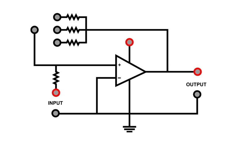
Diagram representation
Visually representing the circuit design using detailed diagrams is helpful in understanding the physical arrangement and connections of components within the non-inverting amplifier circuit. A well-illustrated diagram not only helps with understanding, but also serves as a reference point for troubleshooting and further changes.
For example, adding labels for each component and their specific values on the diagram will make connections clearer and easier to understand for beginners and enthusiasts alike. Additionally, a graphical representation helps identify potential areas for improvements or changes to the circuit design.
When designing a non-inverting amplifier circuit, careful consideration must be given to the selection, sizing, and visual representation of components. By paying close attention to resistor selection and op-amp sizing and using detailed diagrams, you can create a robust, non-inverting amplifier circuit that meets specific gain requirements while ensuring stability and performance.
The next section describes methods for optimizing gain matching to increase your amplifier's performance.
Get tuning for optimal performance
After designing your non-inverting amplifier circuit, the next step is to adjust the gain for optimal performance. The gain of an amplifier determines how much the amplitude of the output signal increases compared to the input signal. This adjustment is crucial because it affects the overall functionality and efficiency of the amplifier. Let's take a closer look at this tuning process and see why it's so important.
Profit calculation
When adjusting the gain of your non-inverting amplifier, be sure to calculate the gain required for your application. The gain factor, denoted as Av, can be calculated using a simple formula: Av = 1 + (Rf/R1). Rf represents the feedback resistance and R1 is the input resistance. By manipulating these resistor values, you can achieve the desired gain level needed for your circuit.
You can adjust the gain for different applications by carefully manipulating these resistance values. For example, you may need higher gain to drive speakers for audio amplification. At the same time, you may need smaller, finer gain adjustment to obtain accurate sensor values at the sensor interfaces. Calculating these adjustments ensures that the amplifier operates within the desired voltage ranges and amplifies input signals effectively and without distortion.
To better understand this process, let's look at some real-world scenarios where gain adjustments are essential. For example, you may need a higher gain in audio amplification to drive the speakers and provide sufficiently clear sound quality. In sensor interface circuits, however, accuracy is critical and small gain adjustment may be necessary to ensure accurate interpretation of sensor data.
For example, if you are designing an instrument circuit to accurately measure small signal voltages, accurate gain adjustment is critical to maintaining accurate measurements without adding additional noise or distortion. Understanding and implementing different gain settings based on specific application requirements is critical to achieving optimal circuit performance in any scenario.
Knowing how to accurately calculate and implement gain adjustments will allow you to optimize your non-inverting amplifier circuit according to specific application requirements. Let's explore practical steps to adjust these settings for real-world scenarios.
Importance of input impedance
Impedance is a term commonly used in audio systems and electrical devices, and for good reason. Simply put, it acts as a gatekeeper, determining how much your device resists or allows the flow of electricity. For non-inverting amplifiers, input impedance plays a critical role in maintaining the integrity of signals entering the amplifier.
Imagine you have a musical instrument that you want to connect to an amplifier. The instrument is designed to output a specific signal, and you want the entire signal to pass to the amplifier without interference. If the amplifier has a low input impedance, it's like trying to pour water from a small pipe into a large bucket – you're not using the full potential of your instrument's output. On the other hand, the high input impedance means it's like pouring water from a small pipe into a small bucket – everything goes exactly where it's supposed to go.
Avoiding loading effects
The input impedance serves as a welcome gate for incoming signals. An amplifier with high input impedance draws very little current from the source and does not disturb or load the source. This means that the signal source does not have to work hard or lose quality to ensure that the signal reaches its destination without anything being lost in transmission.
For example, if your guitar outputs a 10 millivolt signal and your amplifier's input impedance is 1 megohm (1 million ohms), this valuable signal will pass through almost completely unscathed. On the other hand, an amplifier with low input impedance (say 1 kOhm) would draw more current and thus dissipate more signal power at the source, resulting in a weakened output signal and an overall degradation in sound quality.
It is important to note that a low input impedance can cause loading effects on the input signal source, but an input impedance that is too high can cause noise problems due to increased susceptibility to external interference.
Finding this input impedance sweet spot is critical to maintaining signal integrity and ensuring that our non-inverting amplifiers provide accurate and faithful representations of the original signal.
Calculations and practical applications
Practical application of understanding input impedance ensures that our signal source is not subject to unnecessary compromise. It is about creating an environment in which electrical current can flow with minimum resistance and maximum potential.
Think of it like building good roads: When traffic flows smoothly and efficiently, everyone gets to their destination without slowing down or hitting obstacles. Likewise, adequate input impedance ensures that signals travel smoothly through our circuits without obstacles.
Now that we know why input impedance is so important, let's explore how it is calculated and what practical implications it has on signal integrity using real-world examples.
Dealing with source and load impedances
With non-inverting amplifier circuits, it's not just the gain or input impedance that matters; Source and load impedance plays a critical role in maintaining signal integrity and overall performance. Source impedance is the resistance or impedance that the amplifier sees at its input. In contrast, load impedance is the resistance or impedance presented to the amplifier at its output.
Source impedance considerations
Source impedance can affect the accuracy of your amplifier's output, especially when connected to a sensor or microphone with significant internal resistance. If the source impedance is high compared to the amplifier input impedance, it can cause signal loss and distortion. To avoid this, it is necessary to ensure that the source impedance is much lower than the input impedance of the non-inverting amplifier. One way to achieve this is to use a buffer between the source and the amplifier. A buffer with high input impedance and low output impedance effectively isolates the source from load effects and ensures that the signal remains intact.
For example, let's consider a scenario where the non-inverting amplifier is connected to a sensor with a relatively high internal resistance. Without properly considering the source impedance, the accuracy of the amplified signal can be compromised. By introducing a high input impedance buffer, the sensor signal remains unaffected by amplifier loading effects and its fidelity is maintained.
Effects of load impedance
On the other hand, load impedance directly affects the signal the amplifier provides to subsequent stages or loads, such as other amplifiers or filters. Ensuring compatibility between the output impedance of the non-inverting amplifier and the input impedance of the next stage is critical to maintaining signal fidelity and avoiding signal degradation.
If the amplifier's output impedance exceeds the load impedance, this can result in signal loss and distortion as too much current is drawn from the output stage. However, if it is too high, it may result in reduced power transfer efficiency and affect frequency response.
Strategies for maintaining signal fidelity

To maintain signal fidelity and ensure seamless signal transfer between stages, overall system performance can be significantly improved by appropriately matching the output impedance of the non-inverting amplifier with subsequent loads or by employing buffering techniques.
Understanding these potential pitfalls related to source and load impedances provides valuable information about optimizing non-inverting amplifier circuits for better performance and reliability.
Overcoming Common Tradeoffs and Problems
Even after optimizing the input impedance of the non-inverting amplifier circuit, you may encounter common problems that affect signal processing. One of these problems is the input offset voltage, which affects the accuracy and precision of amplification. It causes errors by introducing an undesirable constant voltage to the operational amplifier input terminals, resulting in inaccuracies and signal distortions.
To reduce the input offset voltage and ensure accurate gain, there are techniques to neutralize this offset voltage. One such method is “offset zeroing,” which actively adjusts voltages within the amplifier circuit to eliminate unwanted offset voltages. This allows for precise adjustments to counteract the effects of input offset voltage, resulting in more accurate amplification and signal processing.
Practical examples and solutions
If you have a problem with the input offset voltage, you can calibrate and compensate the input voltage with a potentiometer or other adjustable components to neutralize the offset voltage and obtain a more accurate and stable output signal. By implementing practical solutions like these, electronics enthusiasts can solve input offset voltage issues and improve the performance of their non-inverting amplifier circuits.
In addition to compensation voltage management, other common problems that can arise in non-inverting amplifier circuits include noise, distortion, and stability issues. These issues significantly impact signal processing fidelity and reliability and require effective mitigation strategies to ensure optimal circuit performance.
To minimize interference and maintain signal integrity when dealing with noise and distortion in non-inverting amplifier circuits, it is important to pay close attention to grounding techniques, signal shielding, and component placement. Additionally, the use of high-quality components with low-noise characteristics can reduce unwanted noise and distortion in amplified signals.
With regard to stability issues, careful consideration of feedback network design, sufficient offsets, and appropriate compensation techniques can improve the stability and robustness of non-inverting amplifier circuits.
By exploring practical examples and tackling these common challenges head-on, electronics enthusiasts can gain the knowledge and skills needed to overcome common tradeoffs and problems in non-inverting amplifier circuits, thereby improving the quality and reliability of their electronic projects.
Learn more about amplifiers and improve your understanding of electronics by visiting our amplifiers website.


