With the advancement of metallurgical technology, various high-quality stainless steels are continuously emerging. Despite the metallurgical industry's ability to constantly develop superior steel grades, adequate heat treatment is necessary to optimize the functionality of stainless steel.
During the heating and cooling processes of different types of steel, the transformation of the matrix structure varies, as does the generation and transition of carbides, nitrides and intermetallic compounds, which influence the performance of stainless steel differently.
Therefore, the appropriate heat treatment process must be selected based on the type of steel and the intended application during heat treatment of stainless steel.
Austenitic Stainless Steel Heat Treatment
1. Purpose of heat treatment of austenitic stainless steel
Austenitic stainless steel has an austenite matrix structure. During the heating and cooling process, there is no transformation of the martensitic phase, therefore there is no hardenability.
The objective of austenitic heat treatment is to increase corrosion resistance, mitigate the adverse effects brought by the secondary phase, relieve stress or soften the material that has already undergone hardening.
2. Fundamental Theories
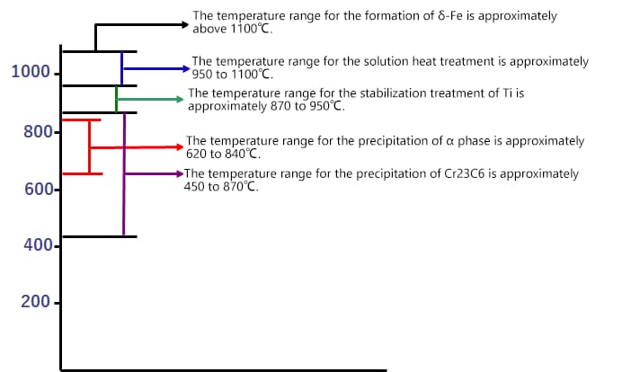
(1) Precipitate generation temperature
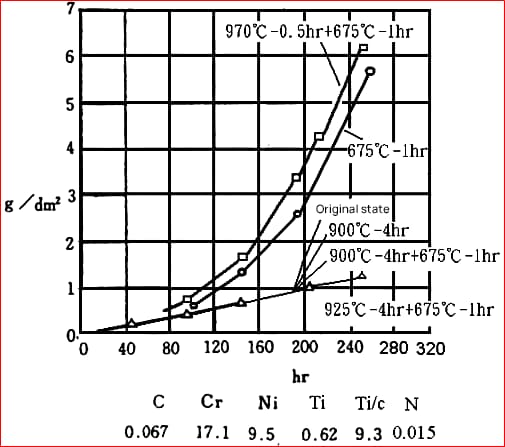
(2) Precipitation and Dissolution of Alloy Carbides
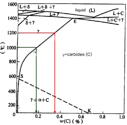
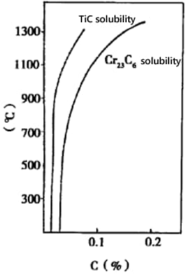
1) Carbon solubility
For 304 steel (18Cr-8Ni), the solubility of carbon at 1200°C is 0.34%, at 1000°C is 0.18% and at 600°C is 0.03%.
The carbon content in 304 steel does not exceed 0.08%. Above 1000°C, carbon dissolves in austenite. Given the small radius of carbon atoms, as the temperature decreases, carbon precipitates along grain boundaries.
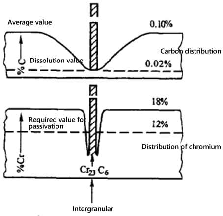
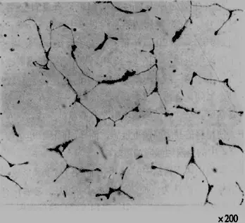
2) Intergranular chromium depletion
Solubility of carbon: As the temperature drops, the solubility decreases.
Atomic radius of carbon: Smaller atomic radius means lower solubility, leading to precipitation along grain boundaries.
Stability: Precipitated carbon atoms are unstable and form stable compounds with chromium and iron, such as Cr23C6 or (FeCr)23C6.
Atomic diffusion rate: The smaller radius of carbon atoms results in a higher diffusion rate. On the other hand, the larger radius of chromium atoms results in a lower diffusion rate.
(3) Sigma Phase
1) Training Conditions:
– Prolonged heating in the temperature range of 620~840°C.
– The addition of ferrite-forming elements, such as Titanium (Ti), Neodymium (Nd), etc.
– Use welding rods with a high content of ferrite-forming elements in the welding seam.
– In austenite with Manganese (Mn), Nitrogen (N) replacing Nickel (Ni).
2) Adverse effects:
– Reduced plasticity, especially impact toughness.
– The sigma phase is a rich intermetallic compound, its formation can easily lead to intergranular corrosion and corrosion in chloride (Cl-) media.
(4) Delta Ferrite
1) Training conditions:
In chromium-nickel cast austenitic stainless steel, the chemical composition of the molten state is irregular, leading to regions rich in ferrite-forming elements.
In the welding structure of some austenitic stainless steels.
2) Beneficial effects:
Containing 5-20% delta ferrite can reduce intergranular corrosion.
Increases yield resistance.
Under low stress conditions, it may decrease susceptibility to stress corrosion cracking.
During welding, it reduces the likelihood of thermal cracks.
3) Adverse effects:
During processing under pressure, cracks can easily occur due to the different deformation capabilities of the two structures.

3. Heat Treatment Process
(1) Solution treatment
1) Solution treatment temperature: 950-1150°C
2) Insulation time: 20-30% longer than general alloy steel.
3) Cooling: Rapid cooling is required in the carbide forming temperature range (450-850°C).
The following principles are applicable to cooling methods:
- For chromium content greater than 22% and with high nickel content;
- For carbon content greater than 0.08%;
- For stainless steel with a carbon content of no more than 0.08%, but with an effective size of more than 3 mm, water cooling is selected;
- For stainless steel with a carbon content of no more than 0.08% and an effective size of less than 3 mm, air cooling is selected;
- For thin parts with an effective size of less than 0.5 mm, natural cooling can be used.
| JIS | Ripening temperature in Celsius. | Cold working method |
| SUS 403 | 1010-1150 | Rapid cooling |
| SU 304H | Above 950 | Rapid Cooling |
| SUS 304L | 1010-1150 | Rapid cooling |
| SUS 321 | 920-1150 | Rapid cooling |
| SUS 321H | Cold working requires a hardness greater than 1095. | Rapid cooling |
| Hot working requires a hardness greater than 1050. | Rapid cooling | |
| SUS 316 | 1010-11S0 | Rapid cooling |
| SUS 316H | Above 985 | Rapid cooling |
| SUS 316L | 1010-1150 | Rapid cooling |
| SUS 316JI | 1010-1150 | Rapid cooling |
| SUS 316JIL | 1010-1150 | Rapid cooling |
| SUS 301 | 1010-1150 | Rapid cooling |
| SUS 302 | 1010-1150 | Rapid cooling |
| SUS 309S | 1030-1180 | Rapid cooling |
| SUS 310S | 1030~1180 | Rapid cooling |
| SUS 347 | 980~1150 | Rapid cooling |
| SUS 347H | Cold processing from 1095 and above | Rapid cooling |
| High temperature processing of 10S0 and above. | Rapid cooling | |
| SUS 303 | 1010-1150 | Rapid cooling |
| SUS 305 | 1010-1150 | Rapid cooling |
| SUS 30SM | 1010-1150 | Rapid cooling |
| SUS 317 | 1010-1150 | Rapid cooling |
| SUS 317L | 1010-1150 | Rapid cooling |
| SUH 31 | 950-1150 | Rapid cooling |
| SUH 309 | 1030-1150 | Rapid cooling |
| SUH 310 | 1030-1180 | Rapid cooling |
| SUH 330 | 1030-1180 | Rapid cooling |
(2) Stabilizing Treatment
Stabilization treatment is a heat treatment method used for austenitic stainless steel containing Nd or Ti.
1) Stabilization treatment temperature: Higher than the dissolution temperature of chromium carbides (450-870 ℃), but lower or slightly higher than the dissolution temperatures of TiC and NbC (750-1120 ℃). The general recommendation is 870-950 ℃.
2) Soaking time: 2-4 hours (depending on part shape, alloy elements, etc.). The soaking time for those with a thickness or diameter of 25 mm is 2 hours, with an additional hour added for larger sizes.
3) Cooling: Slow cooling rates such as air cooling or furnace cooling.
(3) Stress relief annealing
1) The stress relief annealing process for austenitic stainless steel should be selected based on the material properties, operating environment, stress relieving purpose, and the size and shape of the workpiece.
2) The objectives of stress relief annealing are:
- To remove residual stresses, reducing stress corrosion cracking;
- To guarantee the final dimensional stability of the part.
3) Stress corrosion cracking
| Steel Grade | Heat treatment | Residual stress in kgf/mm 2 | The moment when rupture occurs when boiling 42% MgCl2 (at 154 degrees Celsius). | ||||
| Circumferential direction | Longitudinal direction | ||||||
| 304 | Cooling state (tensile strength 115.9 kg/mm 2 ) | 32.4 | 48.3 | 7.5 | Fracture | ||
| Medium-hard condition (tensile strength 93.2 g/mm2) | – | – | 6 | Fracture | |||
| 540°C | 24 hours | Air cooling | – | – | 7.5 | Fracture | |
| 650 | 0.5 | Air cooling | – | – | 22 | Fracture | |
| 650 | 8 | Air cooling | – | – | 14.5 | Fracture | |
| 745 | 0.5 | Air cooling | 1.3 | 5.9 | 245 | Minor fracture | |
| 745 | 0.5 | False cooling | – | – | 292 | A break | |
| 870 | 0.5 | Air cooling | – | – | >292 | No fracture | |
| 870 | 0.5 | False cooling | – | – | >292 | No fracture | |
| 870 | 24 | Air cooling | – | – | >292 | No fracture | |
| 316 | Cooling condition 1/4H (tensile strength 80.4 kg/mm2) | 36.7 | 14.7 | 7.5 | Fracture | ||
| In-place heat treatment and cooling correction (tensile strength 64.3 kg/mm2) | 11.9 | – | 7.5 | Fracture | |||
| 540°C | 24h | – | 31.5 | – | 7.5 | Fracture | |
| 650 | 0.5 | – | 27.3 | – | 7.5 | Fracture | |
| 650 | 8 | – | – | – | 14.5 | Fracture | |
| 745 | 0.5 | – | 18.7 | – | 22 | Fracture | |
| 745 | 0.5 | – | 16.3 | – | 22 | Fracture | |
| 745 | 8 | – | – | – | 22 | Fracture | |
| 790 | 0.5 | – | 7.3 | – | 24 | Fracture | |
| 840 | 0.5 | – | 2.5 | – | >240 | No fracture | |
| 870 | 0.5 | Air cooling | 2.5 | 5.8 | >292 | No fracture | |
| 870 | 0.5 | False cooling | – | – | >292 | No fracture | |
| 870 | 24 | Air cooling | – | – | >292 | No fracture | |
4) Annealing method for stress relief
| Types of materials Method Conditions of use and purpose of stress relief. | Type I (Ultra-low carbon) 00Cr19Ni10 00Cr17Ni14Mo2 |
Class II (Including stable elements) 0Cr18Ni10Ti 0Cr18Ni11Nb |
Type III (Other) 0Cri8Ni10 0Cr17Ni12Mo2 |
| For high voltage corrosion environments. | A·B | BA | ① |
| For medium voltage corrosion environments. | ABC | B·A·C | C① |
| For low voltage corrosion environments. | A·B·C·D·E | B·A·C·D·E | C·E |
| Mitigate localized stress concentration. | AND | AND | AND |
| Applicable in intergranular corrosion environments. | A·C② | A·C·B② | W |
| Eliminate substantial residual stress post-processing. | B.C | B.C | W |
| Relieve the stress incurred during the machining process. | ABC | B·A·C | C③ |
| In situations involving significant machining residual stresses and stresses generated during use, as well as extensive and large-section welded components. | A·C·B | A·C·B | W |
| Ensure the dimensional stability of the components. | F | F | F |
Note: The methods in the table are listed in order of priority.
- A: Heat to 1010-1120℃, hold and cool slowly.
- B: Heat to 850-900℃, hold and cool slowly.
- C: Heat to 1010-1120°C, hold and then cool quickly.
- D: Heat to 480-650°C, hold and cool slowly.
- E: Heat to 430-480°C, hold and cool slowly.
- F: Heat to 200-480°C, hold and cool slowly.
Hold time: For every 25mm, hold for 1-4 hours. Longer holding times are required at lower temperatures.
Grades:
- For working in high stress corrosion environments, it is best to use Type IA Steel treatment or Type II B Steel treatment.
- This should be applied when the part becomes sensitized during the manufacturing process.
- If the part is subjected to treatment C after final machining, at this point treatment A or B can be used.