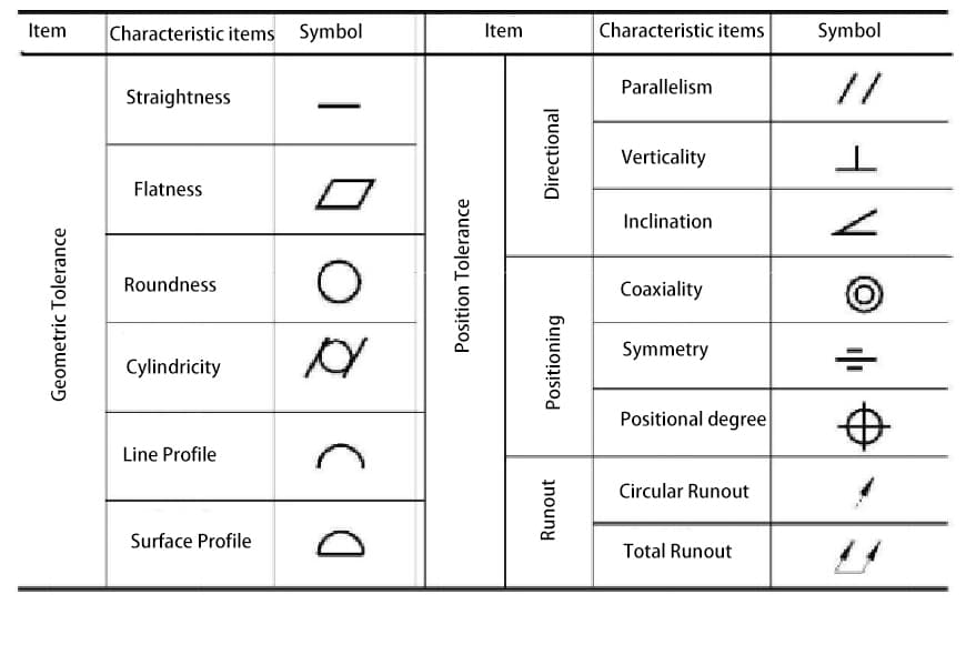
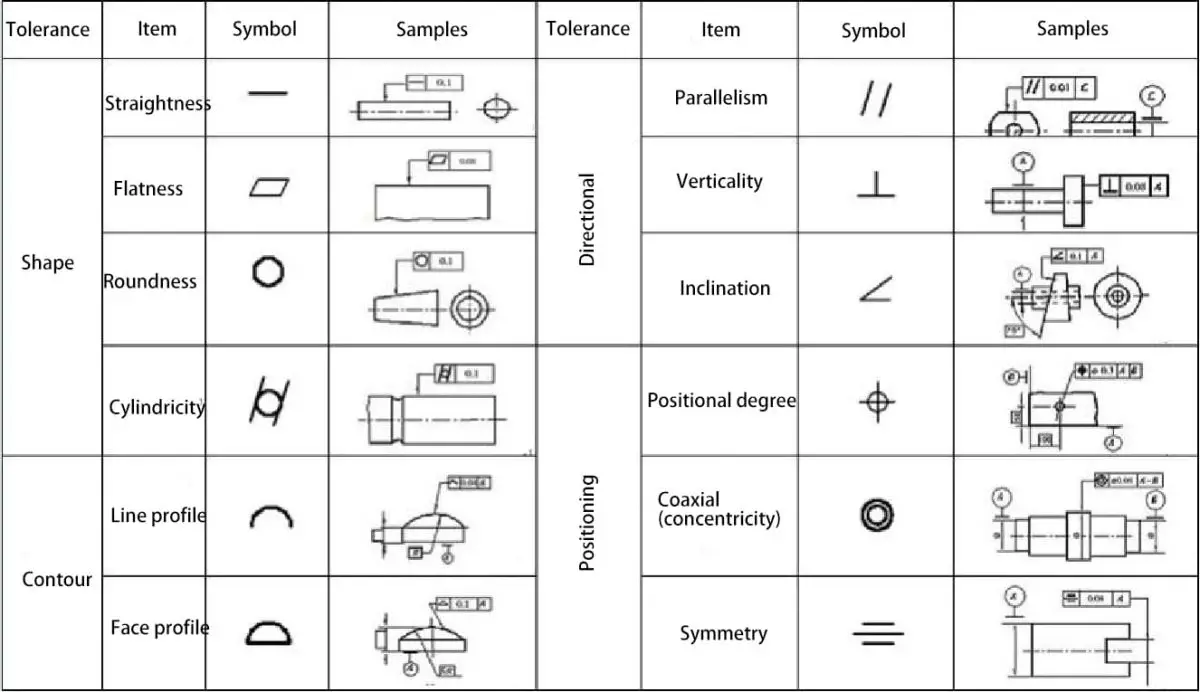
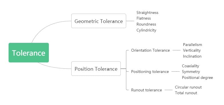
The geometric tolerance specified by the national standard is divided into two categories: geometric tolerance and position tolerance, with a total of 14 items.
Their names and symbols are shown in the table below.
I. Geometric Positioning Tolerance Definition
Straightness – All points are in a straight line, with tolerance specified by the region between two parallel lines.
Flatness – All points on a surface lie in a plane, with a tolerance specified by the region between two parallel planes.
Roundness – All points on a surface lie on a circle, with a tolerance specified by the region between two concentric circles.
Cylindricity – The axis of all points on a rotating surface is equidistant from a common axis. The cylindricity tolerance defines the tolerance region formed by two concentric cylinders, where this rotating surface must fall within this region.
Profile Tolerance – Defines the tolerance method for irregular surfaces, lines, arcs, or common planes. The profile can be applied to a single line element or to the entire surface of a part. The profile tolerance specifies the unique limit along the actual profile.
Perpendicularity – The surface or axis is perpendicular to the reference plane or axis. The perpendicular tolerance specifies one of the following: the region defined by two planes perpendicular to the reference plane or axis, or the region defined by two parallel planes perpendicular to the reference axis.
Parallelism – The surface or axis and all points are equidistant from the reference plane or axis. The parallelism tolerance specifies one of the following: the region defined by two parallel planes or lines parallel to the reference plane or axis, or the cylindricity tolerance region where the axis is parallel to the reference axis.
Coaxiality – The axis of all intersecting composable elements of the rotating surface is the common axis of the data resource. The coaxiality tolerance specifies the region of cylindricity tolerance where the axis is equal to the reference axis.
Position tolerance – Position tolerance defines the area where the central axis or central plane can deviate from the actual (theoretically correct) position.
The basic dimension establishes the actual position between the data resource and the interrelated resource. Position error is the total positional deviation allowed between the feature and its correct position.
For cylindrical features such as holes and outside diameters, the position tolerance is generally the diameter of the tolerance region where the feature axis must fall. For non-circular features (such as grooves and short projections), the position tolerance is the total width of the tolerance region where the center plane of the feature must fall.
Circular offset – Provides control over circular surface elements. When the part rotates 360 degrees, this tolerance is applied independently at any measurement position of the circular element and applied to the circular runout tolerance constructed around the reference axis, controlling the accumulated change in circularity and coaxiality.
When applied to a surface constructed vertically with the reference axis, controls circular elements of flat surface features.
Total Disaster – Provides composite control over all surface elements. When the part rotates 360 degrees, this tolerance is applied simultaneously to circular and elongated features. When applied to a surface constructed around the reference axis, total deviation controls the accumulated variability of roundness, cylindricity, straightness, coaxiality, angle, taper, and profile. When applied to a surface constructed vertically with the reference axis, it controls the accumulated variability of perpendicularity and straightness.
II. Basic Terminology
Feature – refers to the points, lines and surfaces that make up the geometry of a component.
Ideal feature – a feature with geometric meaning.
Actual resource – the resource that actually exists in the component, typically represented by a measured resource.
Reference feature – a feature used to determine the direction or position of the measured feature. Simply referred to as a reference, it serves as the basis for determining the geometric relationship between features. Includes reference points, reference lines, and reference surfaces.
Measured Feature – The feature that specifies the shape or position tolerance.
Central feature – points, lines, or surfaces that have a symmetrical relationship to the feature.
Tolerance range – restricts the variation of actual shape or position features. It is a region defined by a certain maximum error value, determined by size, shape, direction and position.”
III. Tolerance classification
1. Righteousness
The tolerance band is the region between two parallel lines/planes/cylinders, etc. at a distance from the tolerance value t
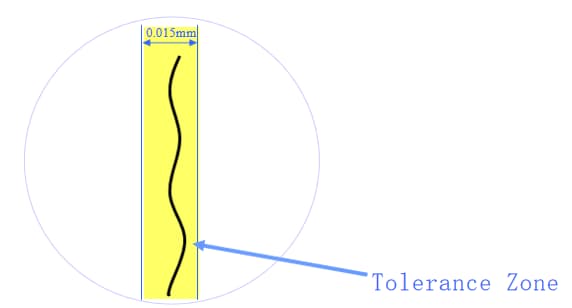
Example 1
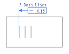
Each engraved line must be located between two parallel lines on the surface with a tolerance value of 0.015mm
Example 2
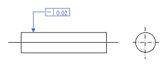
Any element line on the cylindrical surface must be located within the axial plane and between two parallel lines at a tolerance value distance of 0.02 mm.
Application example
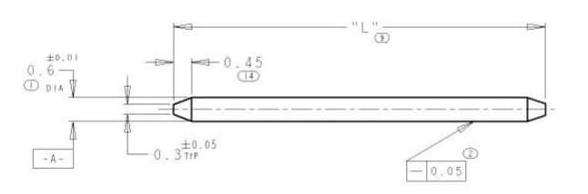
Example 3
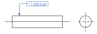
Any element line on the cylindrical surface must be located within the axial plane and between two parallel lines with a tolerance value of 0.04 mm within any 100 mm.
Example 4
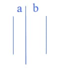
Discussion: How should we understand if different straightness tolerances are given in two directions on the same surface?
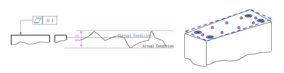
2. Flatness
The tolerance band is the region between two parallel planes at a distance of tolerance value t.
Represents the actual shape of the component's flat features while maintaining the ideal flat condition.
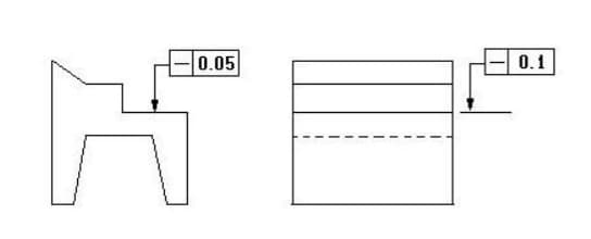
Example 1
The upper surface must be located within two parallel planes with a tolerance value of 0.1 mm.
Example 2
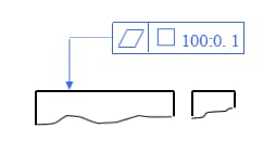
Any 100x100 strip on the surface must be located within two parallel planes with a tolerance value of 0.1 mm.
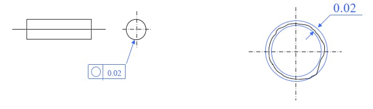
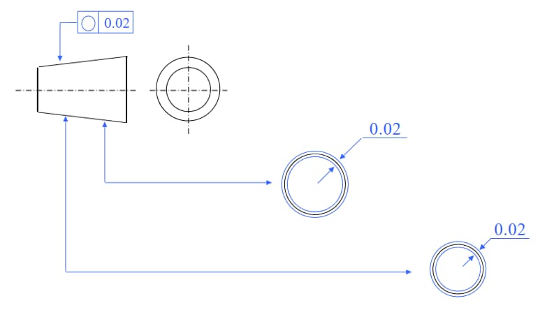
3. Roundness
Represents the actual shape of the circular feature on the component and its center maintaining an equal distance.
The tolerance band is the region between two concentric circles with a difference in radius of tolerance value t in the same cross section.
Example 1
In any cross section perpendicular to the axis, the circle must be located between two concentric circles with a tolerance radius of 0.02 mm.
Example 2
In any cross section perpendicular to the axis, the circle must be located between two concentric circles with a tolerance radius of 0.02 mm.
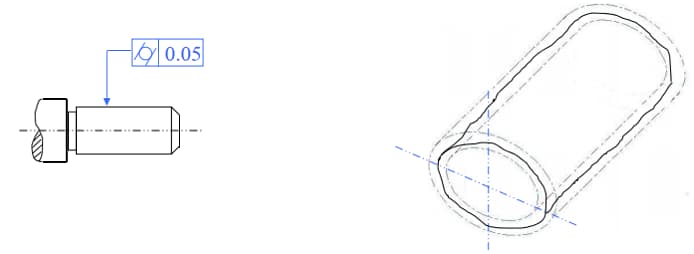
4. Cylindricity
Represents the condition in which all points on the contour of the component's cylindrical surface maintain equal distances from its axis.
The tolerance band is the region between two cylindrical surfaces with a radius difference of tolerance value t on the same axis.
Example 1
The cylindrical surface must be located between two cylindrical surfaces with a difference in radius of tolerance value of 0.05mm on the same axis.
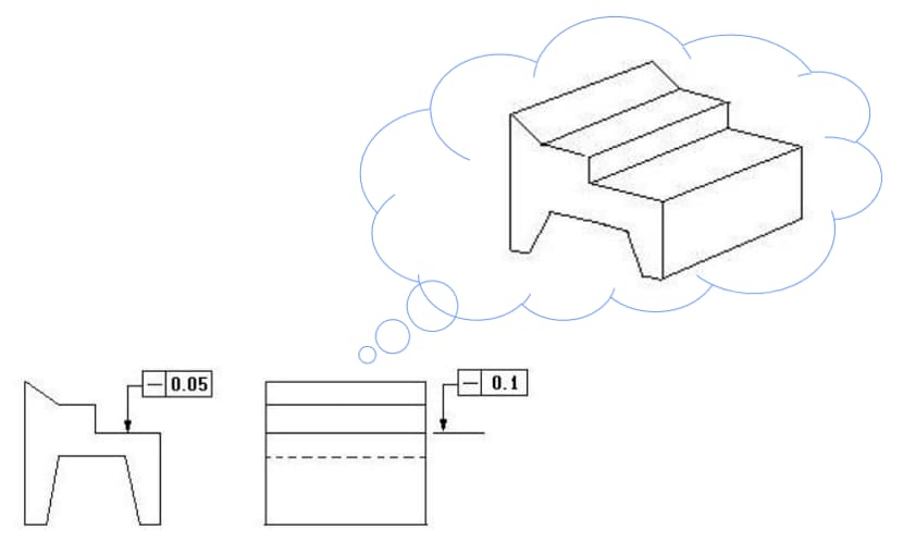
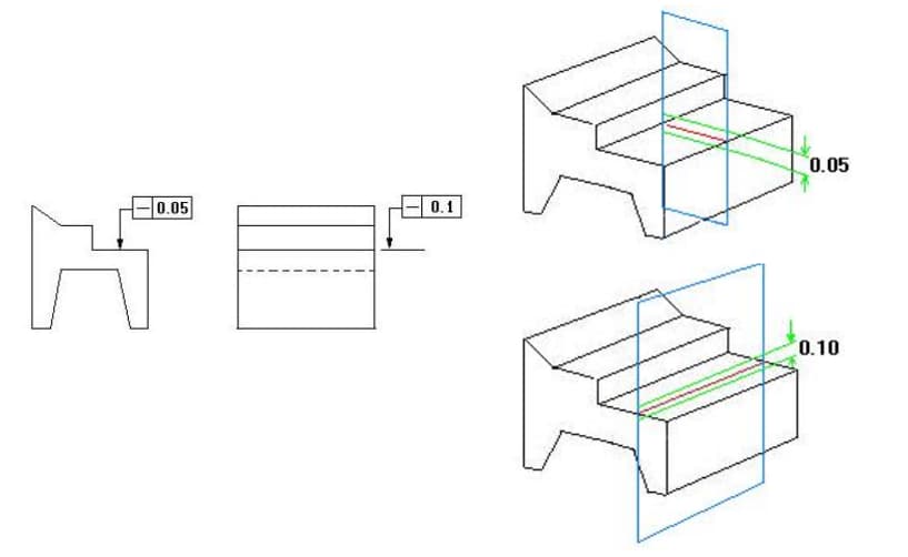
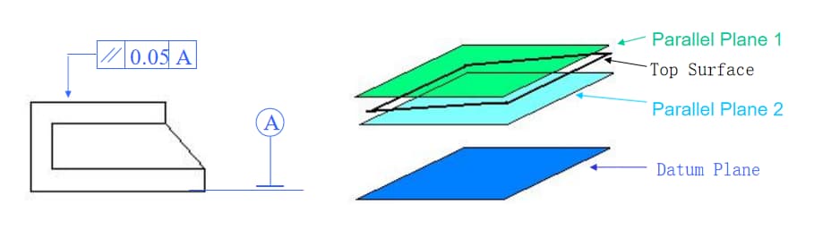
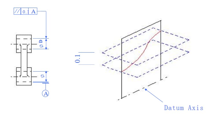
5. Parallelism
Represents the condition where the actual feature measured on the component maintains an equal distance from the reference.
When given a direction, the tolerance band is the region between two parallel planes a distance from the tolerance value t and parallel to the reference plane (or line, axis); when given two perpendicular directions, it is the region within a rectangular prism with dimensions of tolerance values t1×t2 and parallel to the reference axis.
Example 1
The upper surface must be located between two parallel planes at a tolerance distance of 0.05 mm and parallel to the reference plane.
Example 2
The ΦD axis must be located between two parallel planes at a distance of tolerance value 0.1 mm and vertically parallel to the reference axis Φ.
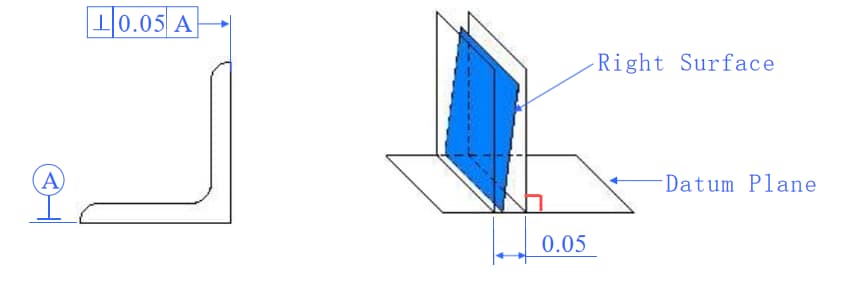
6. Verticality
Tolerance represents the condition in which the actual feature of the part is maintained at a correct angle of 90 degrees to the reference feature.
When given a direction, the tolerance zone is the region between two parallel planes (or lines) that are perpendicular to the reference plane (or line, axis) and separated by a distance equal to the tolerance value t.
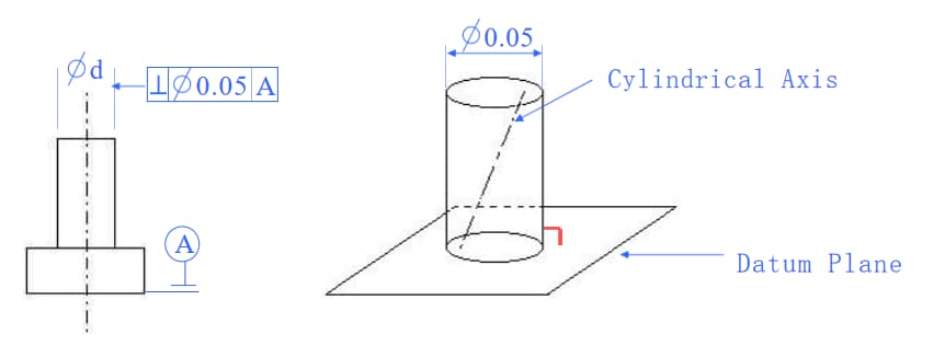
When two mutually perpendicular directions are given, the tolerance zone is the region within a parallelepiped with dimensions t1 × t2 that is perpendicular to the reference axis.
Example 1
The right surface must be located between two parallel planes perpendicular to the reference plane and have a deviation of 0.05 mm.
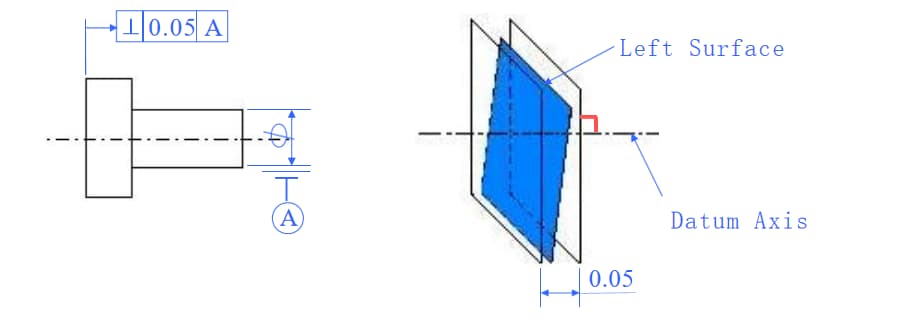
Example 2
The left surface must be within a deviation range of 0.05 mm and between two parallel planes perpendicular to the reference axis.
Example 3
The cylinder axis d must be located within the cylinder surface perpendicular to the reference plane with a diameter tolerance of 0.05 mm.
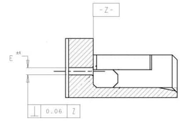
Example 4
The axis of the circular hole E must be between two parallel planes perpendicular to the reference plane Z, with a deviation value of 0.06mm.
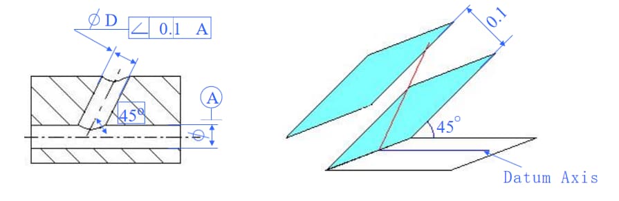
7. Degree of inclination
Correct condition of two elements in the part maintaining a certain angle between their relative directions.
Within a specified direction, the tolerance zone is the area between two parallel planes (or lines) that are at a correct theoretical angle to the reference plane (or line or axis) and a tolerance value distance t from it .
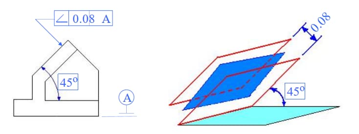
Example 1
The inclined surface must be located between two parallel planes that form an angle of 45 degrees with respect to the reference plane and at a distance of 0.08 mm from it within the tolerance zone.
Example 2
The feature axis D must be located between two parallel planes forming an angle of 45 degrees to the reference axis and at a distance of 0.1 mm from it within the tolerance zone.
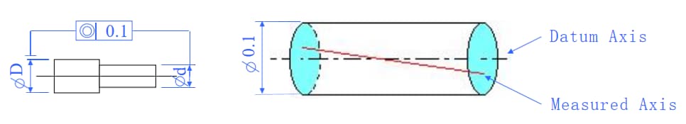
8. Concentricity
Concentricity is the condition in which the axis being measured on the part maintains alignment with the reference axis along the same straight line.
The tolerance zone is the area within a cylinder that has a diameter with the tolerance value t and is coaxial with the reference axis.
Example 1
The feature axis D must be located within a cylinder that has a diameter of 0.1 mm and is coaxial with the reference axis D within the tolerance zone.
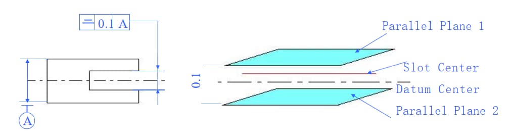
9. Symmetry
Symmetry is the condition in which two pairs of symmetrical features on the part are aligned in the same plane.
The tolerance zone is the area between two parallel planes (or lines) that are a distance of the tolerance value t from the central reference plane (or center line or axis) and arranged symmetrically with respect to it.
If two mutually perpendicular directions are specified, the tolerance zone is the region within a four-sided prism whose cross section is equal to the tolerance values t1 x t2.
Example 1
The central plane of the groove must be located between two parallel planes arranged symmetrically in relation to the central reference plane and at a distance of 0.1 mm from it within the tolerance zone.
Example:
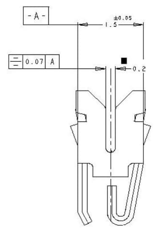
(1) The center of the terminal must be straightened.
(2) The maximum deviation of one side from the center of the groove cannot exceed 0.035 mm.
Question?
(1) How is the displacement T calculated?
T=(ba)/2
(2) What is the symmetry tolerance?
10. Positional tolerance.
Positional tolerance refers to the accuracy of points, lines, surfaces, and other elements of a part relative to their ideal locations.
Tolerance zone:
(1) Point positional tolerance: The tolerance zone is the area within a circle or sphere with a diameter of the tolerance value t, centered on the ideal point position.
(2) Line positional tolerance: When a direction is given, the tolerance zone is the area between two parallel planes (or lines) that are arranged symmetrically around the ideal line position and at a distance from the tolerance value t. If two perpendicular directions are given, the tolerance zone is the area within a four-sided prism with a cross section of size t1 X t2 and the axis line of the prism coincides with the ideal position of the line.
(3) Surface positional tolerance: The tolerance zone is the area between two parallel planes that are arranged symmetrically around the ideal surface position and at a distance from the tolerance value t.
Example 1
The point must be located within a circle with a tolerance diameter of 0.3 mm, and the center of the circle must be in the ideal position of the points determined by relative data A and B.
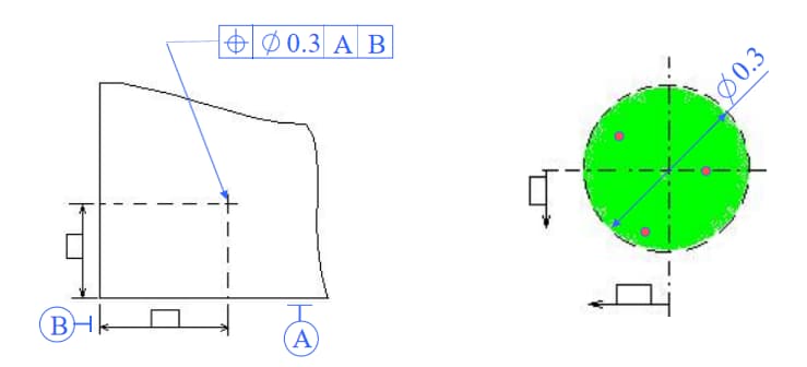
System of three reference planes:
Three mutually perpendicular reference planes A, B and C constitute a system of reference planes, commonly known as the three-plane system of reference. It is the starting point for determining the geometric relationships of various elements in parts.
In the three reference plane system, the reference planes are ordered by their functions.
The most important is the first reference plane (A), followed by the second (B) and third (C) reference planes.
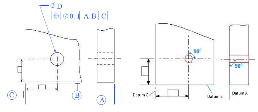
Example 2
The axis of the hole must be located within a cylindrical surface with a tolerance diameter of 0.1 mm, and the axis line of the cylinder surface must coincide with the ideal position of the points in the relative data A, B and C.
Example 3
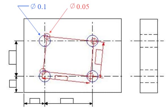
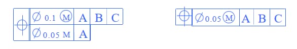
Composite positional tolerance.
Geometric Frame:
It is a graph that shows the correct geometric relationship between a set of ideal axis lines or between them and the reference point.
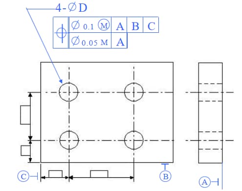
The axis of the four holes D must be located within the overlapping section of two cylindrical tolerance zones, one with a diameter tolerance value of 0.1 mm and the other with a diameter tolerance value of 0.05 mm. The geometric frame of the four 0.1 mm positional tolerance zones is determined with respect to data A, B and C. The geometric frame of the four 0.05 mm positional tolerance zones is oriented only with respect to the reference point A .
The axes of the four D holes must be located within the overlapping section of two cylindrical tolerance zones, one with a diameter tolerance value of 0.1 mm and the other with a diameter tolerance value of 0.05 mm. The geometric frame of the four 0.1 mm positional tolerance zones is determined with respect to data A, B and C. The geometric frame of the four 0.05 mm positional tolerance zones is oriented only with respect to the reference point A .
Consideration: Compare the following two types of positional accuracy.
11. Circular deviation
Refers to the condition in which the rotating surface of the part is limited within the measuring surface and maintains its specified position relative to the reference axis.
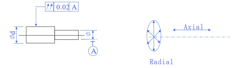
(1) Radial eccentricity.
The tolerance zone is the area between two concentric circles with their centers on the reference axis, where the difference in radius on any measuring plane perpendicular to the reference axis is the tolerance value t.
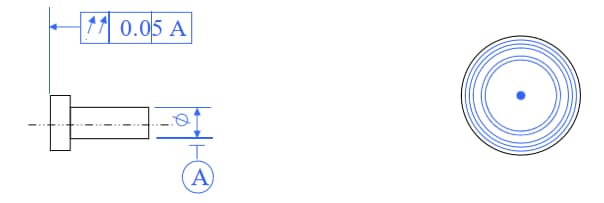
(2) Eccentricity of the end face.
The tolerance zone is the cylindrical surface area along the generatrix direction with width t on the measuring cylinder at any diameter position coaxial with the reference axis.
Example 1
Radial eccentricity.
When the cylindrical surface rotates around the reference axis without any axial movement, the radial deviation in any measuring plane shall not exceed the tolerance value of 0.05 mm.
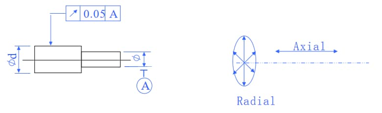
The tolerance zone is the area between two concentric circles with their centers on the reference axis, where the difference in radius on any measuring plane perpendicular to the reference axis is the tolerance value t.
Example 2
End of face deviation.
When the part rotates around the reference axis without any axial movement, the axial deviation at any measuring diameter on the left end face must not exceed the tolerance value of 0.05 mm.
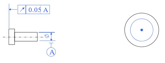
The tolerance zone is the cylindrical surface area along the generatrix direction with width t on the measuring cylinder at any diameter position coaxial with the reference axis.
12. Total disappearance.
Refers to the uniform deviation along the entire measured surface of the part when it continuously rotates around the reference axis
(1) Total radial eccentricity.
The tolerance zone is the area between two cylinders coaxial with the reference axis and having a radius difference of the tolerance value t
(2) Total eccentricity of the end face.
The tolerance zone is the area between two parallel planes perpendicular to the reference axis and a distance from the tolerance value t.
Example 1
Total radial eccentricity.
When the surface continuously rotates around the reference axis without any axial movement, while the indicator moves linearly parallel to the reference axis, the deviation along the entire surface should not exceed the tolerance value of 0.02 mm.
The tolerance zone is the area between two cylinders coaxial with the reference axis and having a radius difference of the tolerance value t.
Example 2
Total eccentricity of the end face.
When the end face continuously rotates around the reference axis without any axial movement, while the indicator moves linearly perpendicular to the reference axis, the deviation along the entire end face should not exceed the tolerance value of 0.05 mm .
The tolerance zone is the area between two parallel planes perpendicular to the reference axis and a distance from the tolerance value t.