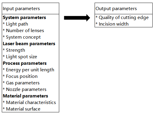
The following factors play a critical role in the laser cutting process:
- Laser mode
- Laser power
- Focus position
- Nozzle height
- Nozzle diameter
- Auxiliary gases
- Auxiliary gas purity
- Auxiliary gas flow
- Auxiliary gas pressure
- Cutting speed
- Sheet material
- Sheet surface quality (e.g. rust, debris, etc.)
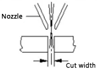
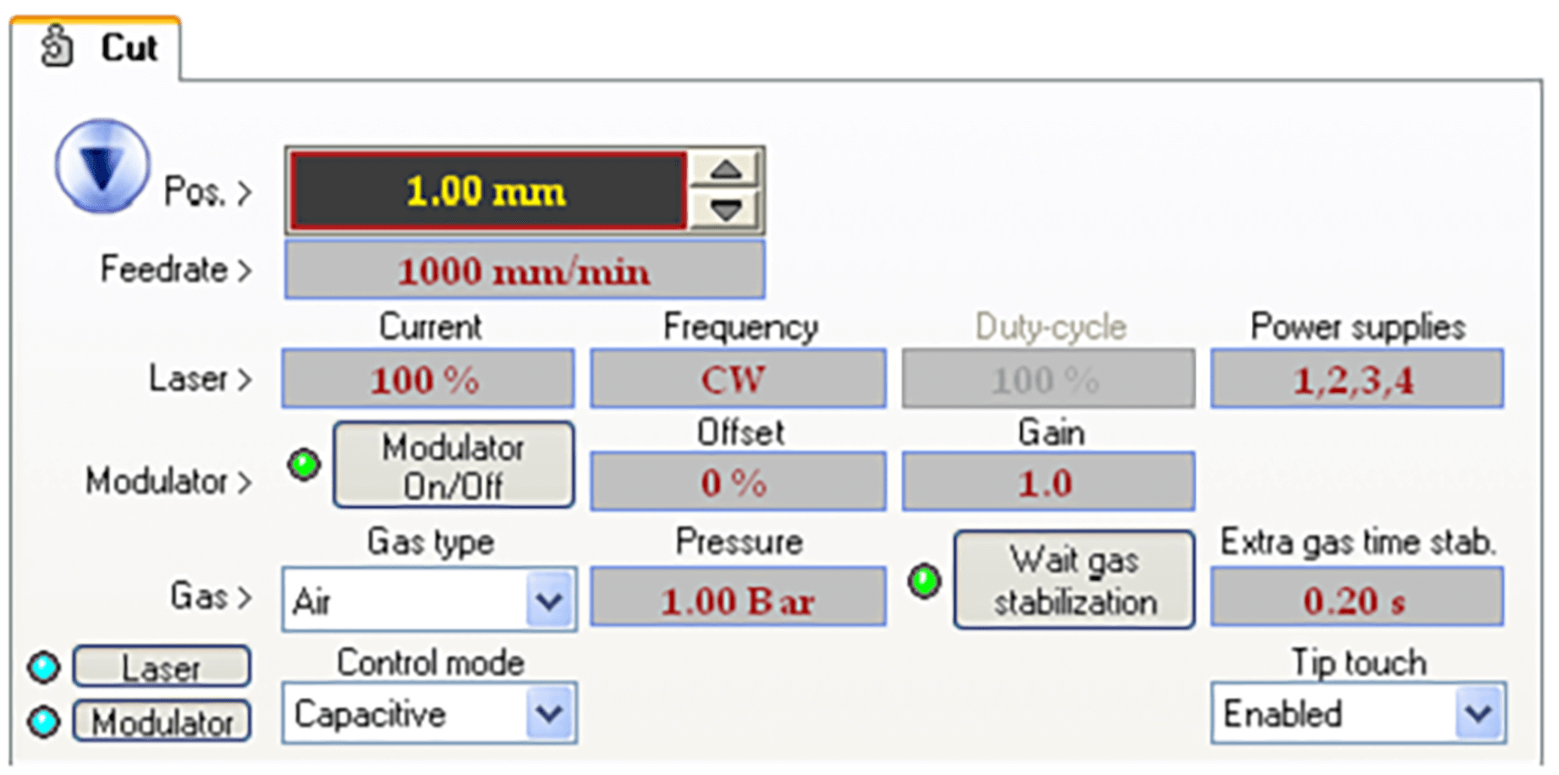
The process parameters associated with laser cutting are shown in the figure below.
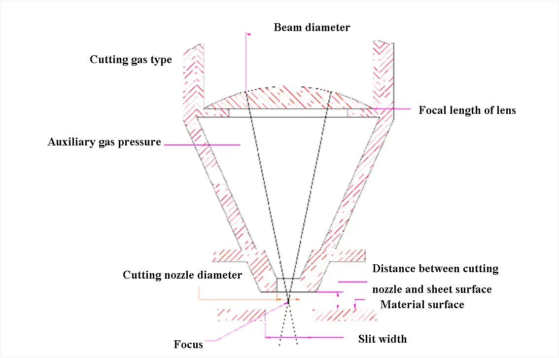
Fig. 1 Cutting process parameters
I. Laser Mode
The laser mode greatly impacts the cutting process and produces better results when cutting steel sheets. This is closely linked to the laser mode and the quality of the external optical lens.
The distribution of light intensity across the cross section of the laser beam is called the transverse mode of the laser. The transverse mode is generally considered to be the laser mode.
Various transverse modes are represented by the symbol TEMmn, where TEM stands for transverse electromagnetic wave and M and N are positive integers representing the ordinal numbers of points with zero light intensity in the X-axis and Y-axis directions, respectively, known as the mode ordinal.
The following figure shows the foci of several different transverse modes of the laser beam. TEM00 mode, also known as basic mode, has no points with zero light intensity. TEM10 mode has a point of zero intensity in the
Laser beams with several transverse modes are called multimode.
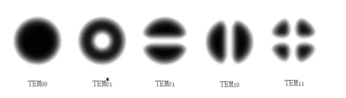
Fig. 2 Spot Mode
In the figure mentioned above, TEM00 mode is referred to as fundamental mode.
TEM*01 mode is a single tap mode and is also known as quasi-fundamental mode. An asterisk * is added to distinguish it from TEM01.
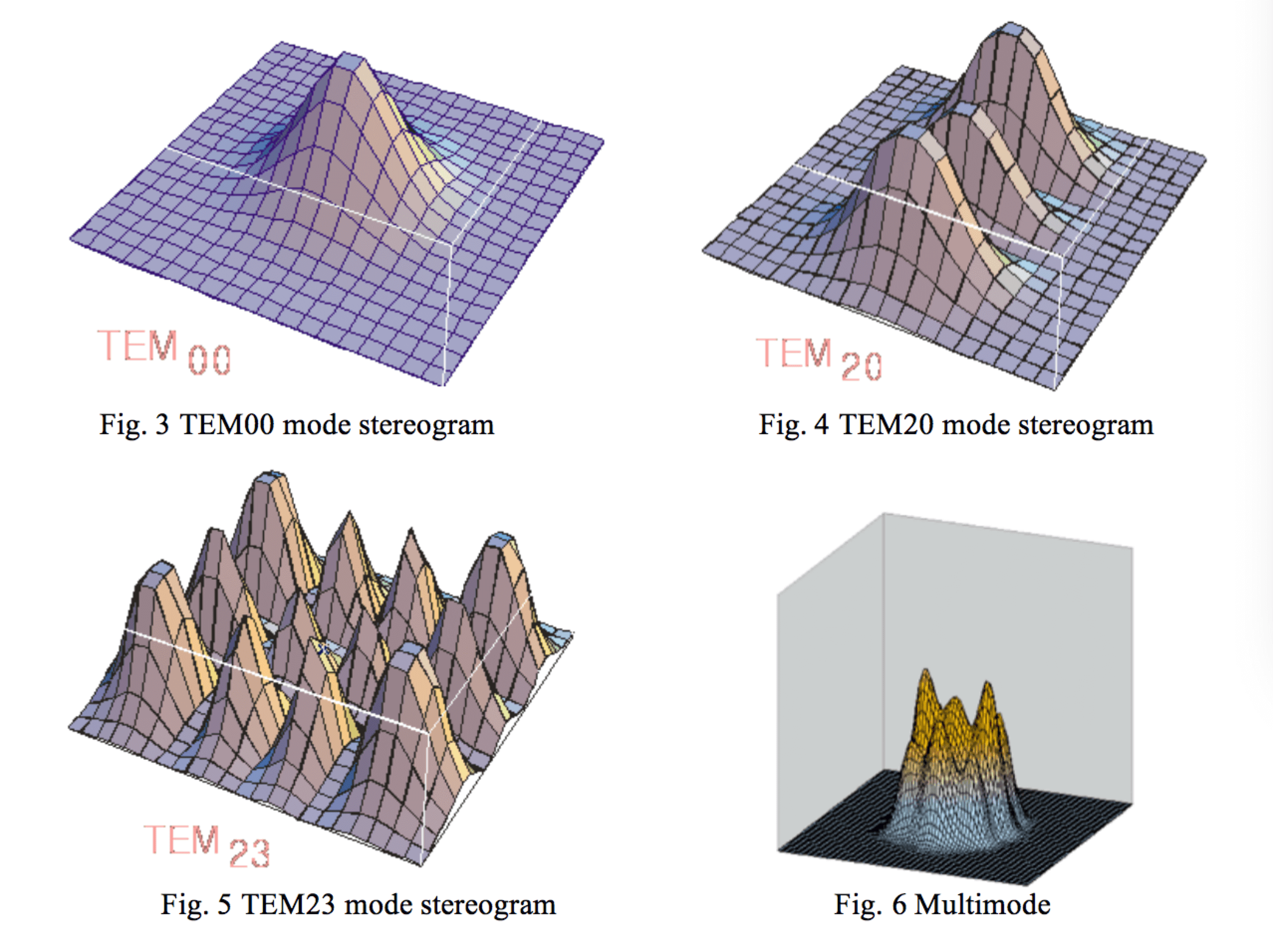
In reality, TEM01 mode and TEM10 mode can be considered the same mode because the X and Y axes are artificially divided. Stereograms of various modes are shown below.
Figure 3: TEM00 mode stereogram
Figure 4: TEM20 mode stereogram
Figure 5: TEM23 mode stereogram
Figure 6: Multimode Stereogram.
II. Focal position
The focus position is a crucial parameter and must be adjusted accordingly.
1. The relationship between the focus position and the cutting surface
| Focal position | Schematic diagram | Characteristics |
| Zero focal length:
The focus is on the surface of the part. |
 |
It is suitable for thin carbon steel below 5mm.
(cut section) 
When the focus is on the upper surface of the workpiece, the cutting result is smooth on the upper surface, but the lower surface is not smooth. |
| Negative focal length:
The focus is under the surface of the workpiece. |
 |
Aluminum, stainless steel and other parts adopt this method.
(cut section)  The focus is located in the center and at the bottom, resulting in a larger smooth surface area. The results indicate that the cutting width is greater and the cutting gas flow is greater with a focus at this location, compared to a focus with zero focal length. Additionally, drilling time is longer in this focus position. |
| Positive focal length:
Focus is on the surface of the workpiece |
 |
When cutting thick steel plates, oxygen is used. Oxidation of the oxygen used in cutting must occur from top to bottom. To accommodate the board thickness, a larger cutting width is required, which can be achieved by adjusting the settings. The cutting section resembles that of gas cutting, with oxygen blowing in and producing a rough section. |
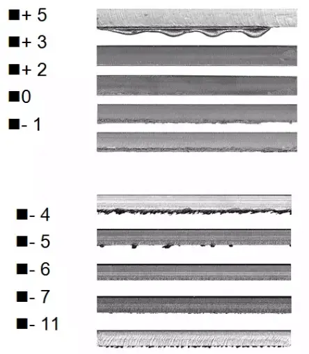
2. The influence of focus position on the cutting section
| 1.5 mm above the surface | 0.5 mm above the surface | 2.5 mm above the surface |
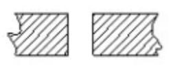 |
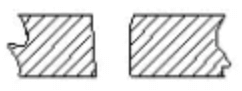 |
 |
3. Focus search
The basic concept is to use masking glue to block the nozzle and adjust the focus distance. Then the size of the holes is checked. The position with the smallest hole is the focus. Finally, the best focus for cutting is determined based on the cutting process after the focus has been found.
III. Nozzle
The nozzle shape, nozzle diameter and nozzle height (the distance between the nozzle outlet and the surface of the workpiece) will affect the cutting result.
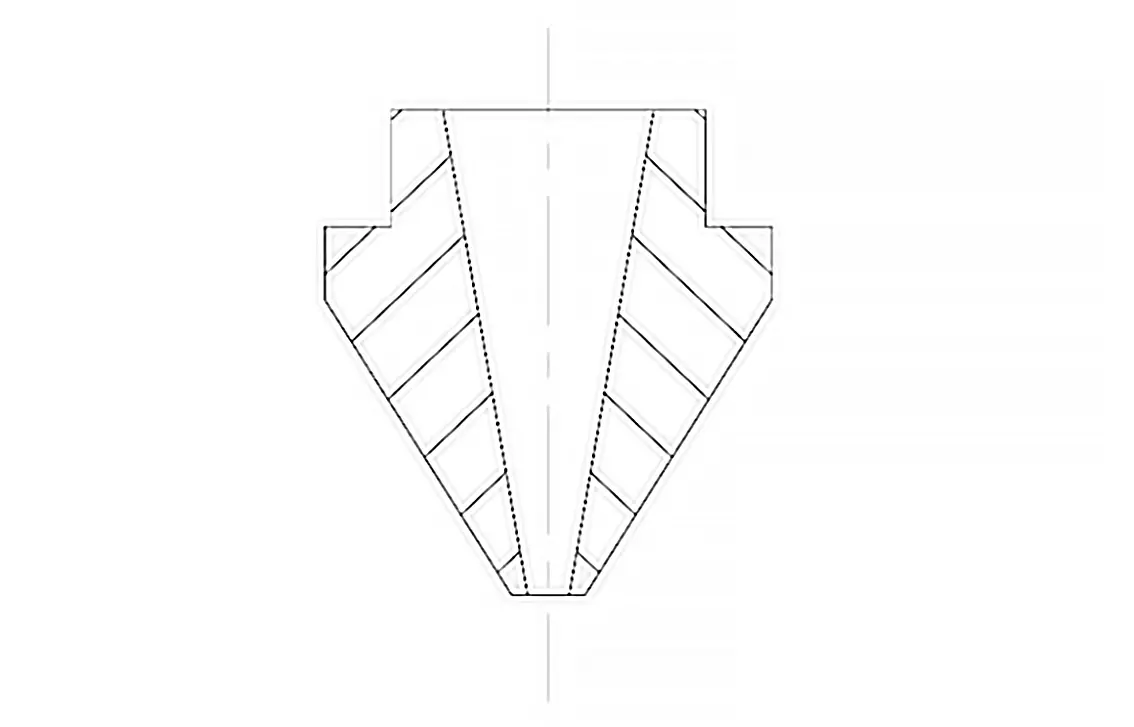
Fig. 7 Nozzle
1. Nozzle function
- Helps prevent impurities, such as melt residue, from jumping up, passing through the nozzle and contaminating the focusing lens.
- Regulates the area and size of gas diffusion to control the quality of the cut.
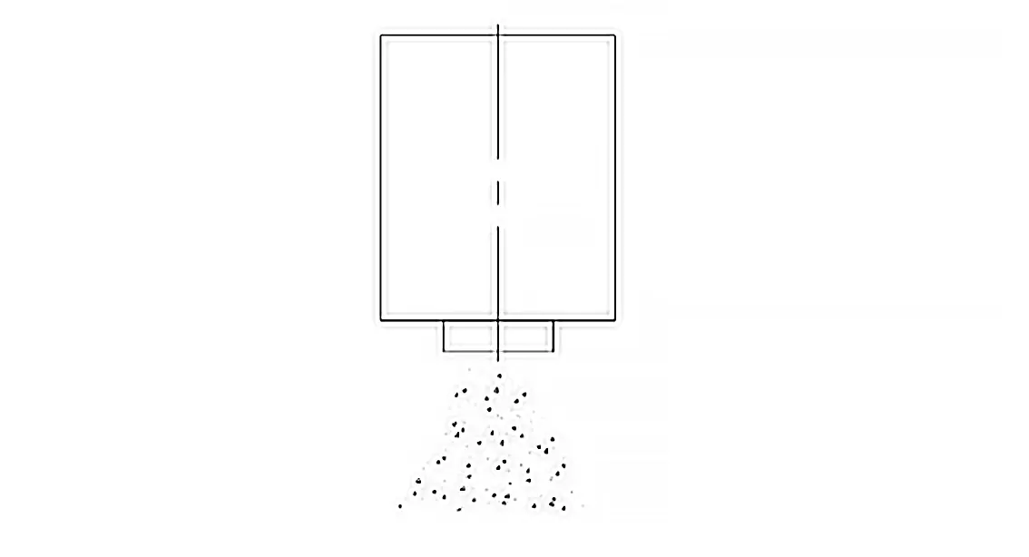
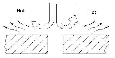
Fig. 8 Gas ejection without nozzle
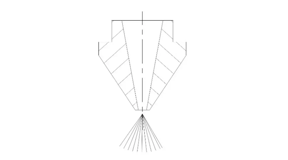
Fig. 9 Gas ejection with nozzle
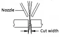
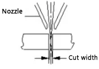
2. The relationship between nozzle and cutting quality
The coaxiality between the center of the nozzle exit hole and the laser beam is one of the important factors that affect the cutting quality. The thicker the piece, the greater the influence. Coaxiality will be directly affected when the nozzle is deformed or there is a melted spot.
Therefore, the nozzle must be stored carefully to avoid damage and deformation. The shape and size of the nozzle have high manufacturing precision, and attention must be paid to the correct installation method.
If the condition of the nozzle is bad, it may be necessary to change the cutting conditions and it is better to replace it with a new one. If the nozzle is not aligned with the laser axis, it will affect the cutting quality as follows.
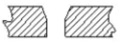
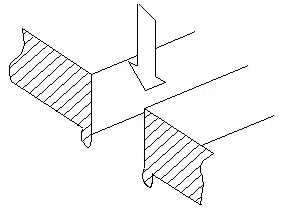
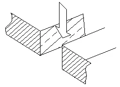
1) Influence on the cutting section
As shown in the figure, when the auxiliary gas is expelled from the nozzle, the volume of the gas becomes uneven, with molten spots on one side but not on the other. The uneven gas volume has little impact when cutting thin sheets less than 3 mm, but becomes more serious when cutting thicker sheets, sometimes even preventing successful cutting.
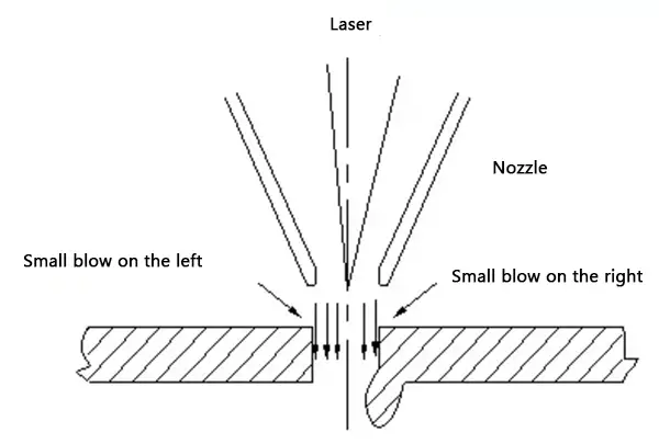
Fig. 10 Influence of coaxiality on the cutting section
2) Impact on sharp corners
If the workpiece has sharp or small angles, it will be subject to excessive melting, which may prevent cutting thick plates.
3) Impact on drilling
Drilling instability, difficulties in controlling timing, excessive melting of thick plates and difficulty in mastering penetration conditions may occur. However, these problems have little effect on cutting thin sheets.
3. Coaxiality adjustment between nozzle orifice and laser beam
The steps to adjust the coaxiality between the nozzle orifice and the laser beam are as follows:
(1) Apply paint to the nozzle outlet end face (generally in red) and attach tape to the nozzle outlet end face as shown in the figure.
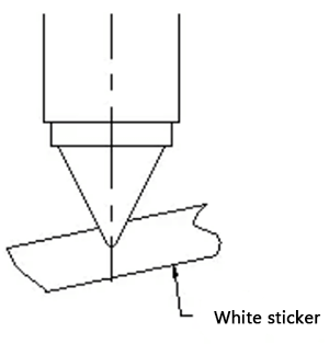
Fig. 11 Coaxial adjustment step 1
(2) Use 10-20 watts power for manual drilling.
(3) Remove the self-adhesive paper, taking care to maintain its orientation for comparison with the nozzle.
Under normal conditions, the laser will burn a black spot on the self-adhesive paper. However, if the center of the nozzle deviates too much from the center of the laser beam, the black dot will not be visible (as the laser beam will hit the nozzle wall).
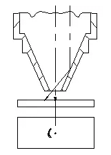
Fig. 12 Nozzle deviation too large
(4) If the center point is too large or small, check whether the conditions are consistent and the focusing lens is secure.
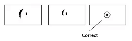
Fig. 13 Loose focus mirror
(5) Note the direction of the black dot relative to the center of the nozzle and adjust the nozzle position accordingly.
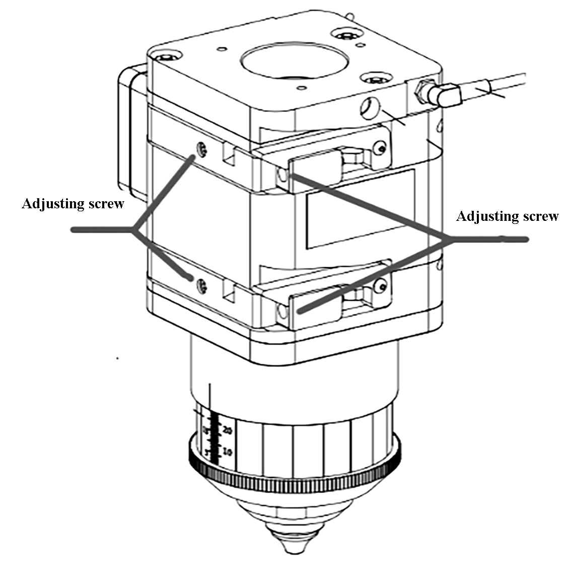
Fig. 14 Adjusting the position of the coaxial laser beam
4. Nozzle diameter
The size of the opening has a crucial impact on the quality of cutting and drilling. If the nozzle opening is too large, melted material may splash during cutting and pass through the nozzle hole, potentially damaging the lens. The larger the aperture, the more likely this is to occur, leading to decreased focusing lens protection and shorter lens life.
Nozzle opening comparison
| Nozzle opening | gas flow rate | Melt Removal Capability |
| Small | Fast | Big |
| Big | Slow | Small |
The difference between φ1 and φ1.5 nozzle
| Nozzle diameter | Thin plate (less than 3 mm) | Thick plate (more than 3 mm)
High cutting power, longer cooling time and longer cutting time |
| φ1 | The cutting surface is good. | The gas diffusion area is small and unstable, but it is basically available. |
| φ1.5 | The cutting surface will be thicker and the corner is easy to have solution stains | The gas diffusion area is large, the gas velocity is slow, and the cutting is stable. |
5. Nozzle height adjustment
Nozzle height refers to the distance between the nozzle outlet and the part surface. The range for setting this height is between 0.5mm and 4.0mm, with a typical setting of 0.7mm to 1.2mm for cutting.
If the height is set too low, the nozzle may collide with the surface of the workpiece. On the other hand, if it is set too high, the pressure and concentration of the auxiliary gas will decrease, leading to a decline in cut quality. When drilling, the height should be a little higher, around 3.5mm-4mm, to prevent the focusing lens from being contaminated by drilling spatter.
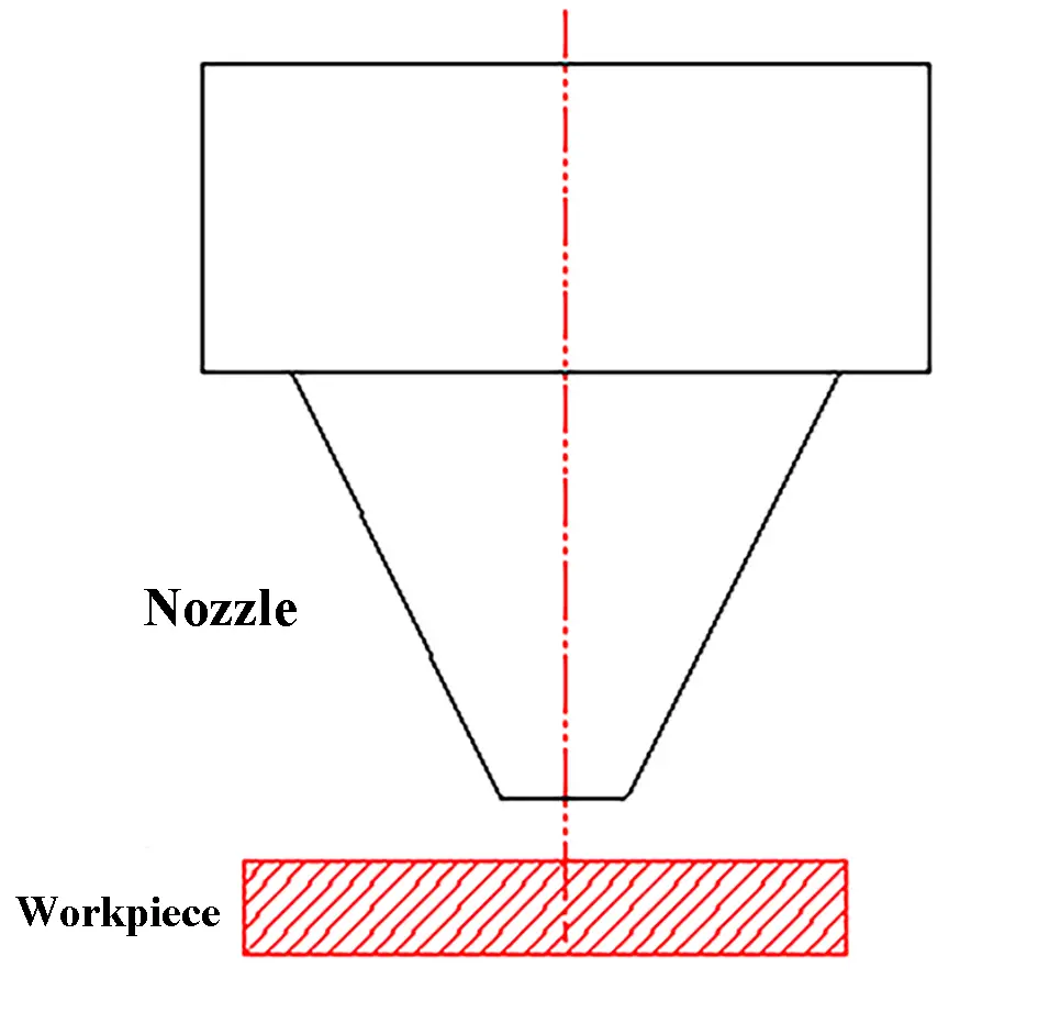
Fig. 15 Nozzle height
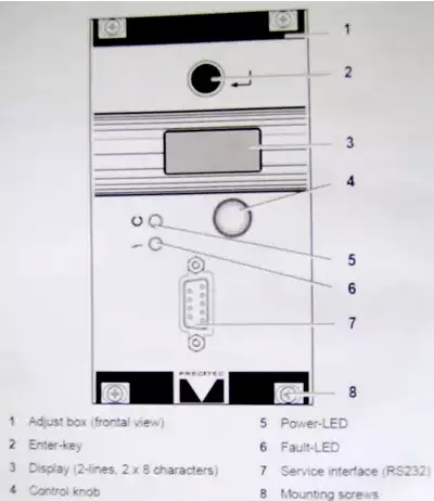
Capacitive Sensor Control Box
As shown in the figure ![]() the nozzle height adjustment item is shown.
the nozzle height adjustment item is shown.
4. Cutting speed
Cutting speed has a direct impact on the width and roughness of the incision. There is an ideal value for cutting speed that varies with material thickness and cutting gas pressure. This value is normally around 80% of the maximum cutting speed.
1. Very fast speed
If the cutting speed is too high, it may cause the following problems:
- Incomplete cuts with random sparks.
- Inconsistent cuts with some areas cut and others not.
- A section of thick cut with no solution.
The cut section will have slanted streaks and solution stains at the bottom.
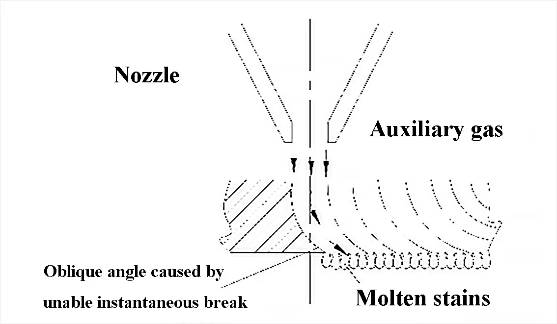
Fig. 18 Very fast speed
2. Very slow speed
(1) Excessive melting leads to a rough cutting surface.
(2) The crack widens and the sharp corners melt.
(3) This impacts cutting efficiency.
3. Determine the appropriate cutting speed
Determine whether to increase or decrease feed speed based on cutting sparks.
1) Sparks spread from top to bottom
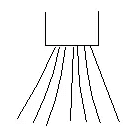
Fig. 19 Normal cutting speed
2) If the spark is inclined, the cutting speed is too fast.
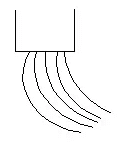
Fig. 20 Cutting speed too fast
3) If the sparks are not diffused and few, and they come together, the speed is very slow.
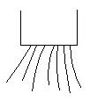
Fig. 21 Cutting speed too slow
The feeding speed is adequate.
As shown in the figure, the cutting surface has a relatively smooth line and there is no melting in the lower half.
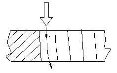
Fig. 22 Normal cutting speed
V. Auxiliary gas cut-off
Consider the following factors when selecting the type and pressure of cutting assist gas:
- Oxygen is typically used to cut common carbon steel with low pressure drilling and cutting.
- Air cutting is commonly used for cutting non-metals.
- Nitrogen is generally used to cut stainless steel.
- Cut quality improves with greater gas purity.
- For cutting low carbon steel sheets, the gas purity must be at least 99.6%, and for cutting carbon steel sheets with a thickness of more than 12 mm, the oxygen purity must be more than 99.9 %.
- The purity of nitrogen for cutting stainless steel sheets must be above 99.6%.
- Greater nitrogen purity results in better quality cuts.
- Low gas purity not only affects cutting quality, but also causes lens contamination.
1. The influence of auxiliary gas on cutting quality
(1) The gas contributes to heat dissipation and combustion, removes solution and improves the quality of the cutting surface.
(2) The effects of low gas pressure on cutting.
The. The cutting surface has melted.
B. The cutting speed cannot be increased, affecting efficiency.
(3) The influence of high gas pressure on cutting quality
The. If the airflow is too high, the cutting surface will be thicker and the seam will be wider.
B. If the air flow is excessive, the cut piece will melt and good cutting quality will not be possible.
2. The effect of auxiliary gas on drilling
(1) When the gas pressure is too low, it is difficult to penetrate and the time increases.
(2) When the gas pressure is too high, the penetration point melts and a large melting area is formed.
As a result, the drilling pressure for thin sheets is higher than that for thick sheets.
3. Gas assist for plexiglass cutting
Plexiglass is flammable. To obtain a transparent and shiny cutting surface, nitrogen or air are chosen as flame retardants. If oxygen is selected, the cut quality will not be good enough. Therefore, it is necessary to select the appropriate pressure based on the actual situation during cutting.
The lower the gas pressure, the brighter the cutting light and the narrower the section of hair. However, if the gas pressure is too low, it will result in slow cutting speed and flame under the plate surface, which can negatively impact the quality of the bottom surface.
SAW. Laser power
The laser power required for laser cutting depends mainly on the type of cutting and the properties of the material to be cut. The highest laser power requirement is for vaporization cutting, followed by fusion cutting and oxygen cutting.
Laser power has a significant impact on cut thickness, speed and incision width. As the laser power increases, the thickness of the material that can be cut increases, the cutting speed accelerates, and the incision width also increases.
Laser power plays a crucial role in determining the cutting process and quality.
1. The power is too small to cut
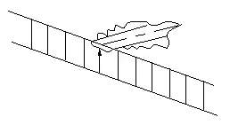
Fig. 26 Very low power
2. If the power is too high, the entire cutting surface will melt.
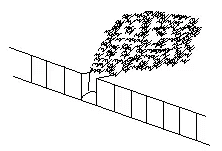
Fig. 27 Excessive power
3. The power is insufficient, resulting in melted spots after cutting.
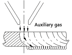
Fig. 28 Energy deficiency
4. The power is appropriate, the cutting surface is good without melted spots .
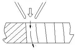
Fig. 29 Adequate power
Summary of cutting parameters
The main parameters of laser cutting
Cutting speed
Given the laser power density and the material, the cutting speed follows an empirical formula. As long as it is above the limit, the cutting speed of the material is proportional to the laser power, which means that increasing the power density can increase the cutting speed.
The cutting speed is also inversely proportional to the density and thickness of the material to be cut. There are several ways to improve cutting speed:
(1) Increase power (in the range of 500-3000W);
(2) Change the beam mode;
(3) Reduce the size of the focus point (for example, using a short focal length lens).
For metal materials, if other process variables remain unchanged, the laser cutting speed can be adjusted within a range while maintaining satisfactory cutting quality. This range appears to be relatively wide when cutting thin metals.
Focus position
After the laser beam is focused, the spot size is proportional to the focal length of the lens. A short focal length lens results in a small spot size and high power density at the focal point, making it ideal for cutting material. However, its disadvantages are a very short depth of focus and a limited adjustment range, making it typically suitable for high-speed cutting of thin materials.
For thicker parts, a telephoto lens with greater focal depth is better suited for cutting, as long as it has sufficient power density.
In most cases, the highest power density is at the focal point, which is usually just on the surface or slightly below the surface of the part when cutting. Maintaining a constant relative position between the focal point and the workpiece is crucial to achieving stable cutting quality.
It is important to note that during operation, the lens may heat up due to insufficient cooling, causing the focal length to change. In such cases, it is necessary to adjust the focal position in a timely manner.
Auxiliary gas
Auxiliary gas is sprayed along the same axis as the laser beam to protect the lens from contamination and remove molten slag at the bottom of the cutting area. For non-metallic materials and some metallic materials, compressed air or an inert gas is used to remove molten and evaporated materials and prevent excessive combustion in the cutting area.
Auxiliary gas pressure
Most metal laser cutting uses a reactive gas (oxygen) to create an exothermic oxidative reaction with the hot metal. This additional heat can increase cutting speed by 1/3 to 1/2.
When cutting thin sheets at high speeds, higher gas pressure is required to prevent the back of the cut from adhering to the slag. When cutting thicker materials or at slower speeds, gas pressure can be reduced as appropriate.
Laser output power
Laser power and mode quality will have a significant impact on cutting. In actual operation, maximum power is often set to achieve high cutting speed or to cut thick materials.
Wrap it up
The above paragraph describes most of the factors that can impact the cutting effect parameters. The following table lists typical values for cutting parameters. These values are not specific to any particular case, but can be used as a reference to determine the correct starting parameters.
Typical values of DC030 stainless steel cutting parameters
|
Thickness (mm) |
Focal length (inch) |
Focus position (mm) |
Laser power (W) |
Cutting speed (m/min) |
Gas pressure N2(bar) |
Nozzle diameter (mm) |
Distance from nozzle to plate (mm) |
|---|---|---|---|---|---|---|---|
| 1 | 5 | -0.5 | 3,000 | 28 | 10 | 1.5 | 0.5 |
| two | 5 | -1 | 3,000 | 8 | 10 | 1.5 | 0.5 |
| 3 | 5 | -two | 3,000 | 4.75 | 15 | 1.5 | 0.5 |
| 4 | 7.5 | -3 | 3,000 | 3.8 | 17.5 | two | 0.7 |
| 5 | 7.5 | -4 | 3,000 | 2.2 | 20 | two | 0.7 |
| 6 | 10 | -5 | 3,000 | two | 20 | 2.2 | 0.7 |
| 8 | 12.5/15 | -6 | 3,000 | 13 | 20 | 3 | 0.7 |
| 10 | 15 | -6 | 3,000 | 0.55 | 20 | 3 | 0.7 |
Typical values of DC030 low carbon steel cutting parameters
|
Thickness (mm) |
Focal length (inch) |
Focus position (mm) |
Laser power (W) |
Cutting speed (m/min) |
Gas pressure O2(bar) |
Nozzle diameter (mm) |
Distance from nozzle to plate (mm) |
|---|---|---|---|---|---|---|---|
| 1 | 5 | 0 | 750 | 9 | 3.5 | 1 | 0.5 |
| two | 5 | -0.5 | 800 | 7 | 3 | 1 | 1 |
| 3 | 5 | -0.5 | 800 | 4 | 3 | 1 | 1 |
| 4 | 7.5 | two | 3,000 | 4.2 | 0.7 | 1 | 1 |
| 6 | 7.5 | two | 3,000 | 3.3 | 0.7 | 1.2 | 1 |
| 8 | 7.5 | two | 3,000 | 2.3 | 0.7 | 1.5 | 1 |
| 10 | 7.5 | two | 3,000 | 1.8 | 0.7 | 1.5 | 1 |
| 12 | 7.5 | two | 3,000 | 1.5 | 0.7 | 1.5 | 1 |
| 15 | 7.5 | two | 3,000 | 1.1 | 0.7 | two | 1 |
| 20 | 7.5 | 2.5 | 3,000 | 0.7 | 0.7 | 2.4 | 1 |
Typical values of cutting parameters for DC025A1Mg3N2 steel
|
Thickness (mm) |
Focal length (inch) |
Focus position (mm) |
Laser power (W) |
Cutting speed (m/min) |
Gas pressure O2(bar) |
Nozzle diameter (mm) |
Distance from nozzle to plate (mm) |
|---|---|---|---|---|---|---|---|
| two | 7.5 | -2.5 | 2500 | 45-6.5 | 10-12 | 1.5 | ≥1.0 |
| 3 | 7.5 | -3.5 | 2500 | 3.0-4.0 | 12-15 | 1.5 | ≥1.0 |
| 4 | 7.5 | -5.0 | 2500 | 1.5-2.0 | 12-16 | 2.0 | ≥1.0 |
| 5 | 7.5 | -5.0 | 2500 | 0.9-1.0 | 12-16 | 2.0 | ≥1.0 |
The following photos show the cutting of 15mm carbon steel and 8mm stainless steel sheets at different focal lengths.