Electroslag welding uses the resistance heat generated by the current passing through the slag as a heat source to melt the filler metal and base metal, which then solidifies to form a tightly connected structure between the metal atoms.
When starting the welding process, short-circuit the welding wire with the welding groove and continuously add a small amount of solid flux.
Use the heat from the electric arc to melt it and form a liquid slag.
When the slag reaches a certain depth, increase the wire feed speed and reduce the voltage so that the wire is inserted into the slag pool and the arc extinguishes, thus entering the electroslag welding process.
Electroslag welding mainly includes electroslag welding with melting nozzle, electroslag welding with non-melting nozzle, electroslag welding with wire electrode, electroslag welding with plate electrode, etc.
Its disadvantage is that the input heat is large, the joint remains at high temperatures for a long time, and the area near the weld is prone to overheating, resulting in coarse crystal molten structures in the weld metal, low impact toughness, and generally requiring post-welding annealing and quenching heat treatment.
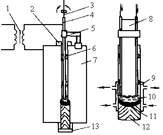
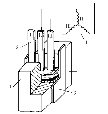
1 – Guide rail
2 – Welding machine head
3 – Welding
4 – Electric nozzles
5 – Slag tank
6 – Metal molten pool
7 – Water-cooled forming slider
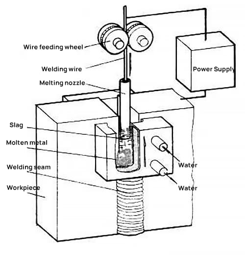
2. Electroslag welding with nozzle electrode
- Welding Wire
- Feed roller
- Electrode holder
- Electrode Steel Tube
- Electrode Coating
- Workpiece
- Water-cooled formation slider.
3. Plate electrode electroslag welding
a) Shape factor ψ = 0.8, large intersection angle Φ, severe central segregation.
b) Shape factor ψ = 3.0, small intersection angle Φ.
5. It has good protection for molten metal.
6. It can weld large and thick parts at one time without chamfering, and the advantage becomes more obvious as the thickness increases.
7. It has low cost.
8. The melting rate is small, generally 10-20%, and the solder composition can be easily adjusted through the welding wire.
9. Preheating is not necessary, but post-welding heat treatment is necessary to improve toughness (generally annealing or tempering).
10. The slag pool has a large heat capacity and is not sensitive to short-term current changes.
6. Common defects and improvement methods for electroslag welding joints
Cracks:
Hot cracks in the center of the welding joint interface.
End of the weld: solidification cracks (reduces the wire feed speed and locally heats the lower part).
Heat-affected zone: cold cracks (pre-heating, post-heating);
Porosity: H2; CO
Slag inclusion: specification change or unstable electrical slag process.
Incomplete penetration: unstable electrical slag process or inadequate specification parameters.
Wide heat-affected zone with coarse grain size: post-welding normalization and tempering heat treatment can be carried out, as well as measures such as gap reduction, addition of filler metal and increasing welding speed.