Cylindrical coordinate robots are robots whose axes form a cylindrical coordinate system. Used for
-assembly operations,
-handling on machine tools,
– spot welding and
-handling in pressure casting machines.
The movement of the main arm is up and down. The robot can perform this movement by extending a cylinder built into the arm. In most cylindrical robots, up and down movement is provided by a pneumatic cylinder and rotation is usually provided by a motor and gears.
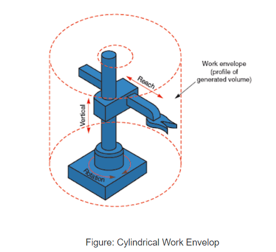 cylindrical work envelope
Cylindrical Robot Construction:
- consists of two orthogonal slides, placed at an angle of 90°, mounted on a rotating axis
• Reach is achieved as the robot arm moves in and out.
• For vertical movement, the car moves up and down a stationary pole, or the pole can move up and down the robot base.
• Movement along three axes plots points on a cylinder
• A cylindrical configuration generally results in a larger work envelope than a Cartesian configuration.
Cylindrical Coordinate System
A cylindrical coordinate system is a three-dimensional coordinate system that specifies positions of points by the distance from a chosen reference axis, the direction of the axis relative to a chosen reference direction, and the distance from a chosen reference plane perpendicular to the axis. The last distance is given as a positive or negative number depending on which side of the reference plane the point faces.
The origin of the system is the point where all three coordinates can be given as zero. This is the intersection between the reference plane and the axis.
The axis is also called cylindrical or longitudinal axis, to differentiate it from the polar axis, which is the radius that lies in the reference plane, starting at the origin and pointing in the reference direction.
The distance from the axis may be called the radial distance or radius, while the angular coordinate is sometimes called the angular position or azimuth. The radius and azimuth are together called polar coordinates, as they correspond to a two-dimensional polar coordinate system in the plane passing through the point, parallel to the reference plane. The third coordinate can be called height or altitude (if the reference plane is considered horizontal), longitudinal position or axial position.
However, cylindrical configurations have some disadvantages.
– Their overall mechanical rigidity is reduced because robots with a rotating axis must overcome the inertia of the object during rotation.
– Its repeatability and accuracy are also reduced in the direction of rotary movement.
– The cylindrical configuration requires a more sophisticated control system than the Cartesian configuration.
Application of cylindrical configurations
Typical applications for cylindrical configurations include the following:
• Loading and unloading machines
• Investment Casting
• Conveyor pallet transfers
• Casting and forging applications
• General material handling and special payload handling and handling
• Meat packaging
• Coating applications
• Set
• Injection molding
• Pressure casting