Air Engine Design and Manufacturing – Mechanical Design
Roberto Magalhães
Air Engine Design and Manufacturing – Mechanical Project
AIR ENGINE
SYNOPSIS
All car engines consume petroleum fuel. Considering the demand and cost of fuel, other energy resources are required to operate the vehicle. So that we opt for another type of energy such as electrical energy, solar energy, etc… It can be noted that air energy is readily available and free. Therefore, we consider this pneumatic motor in our design.
See more information:Air Engine (Compressed Air Engine-CAV)
METHODOLOGY The project consists of the following parts
Control unit
Solenoid valve
Air Inlet Valve
air gun
Spur Gear Arrangement
Rotary axis
Wheel
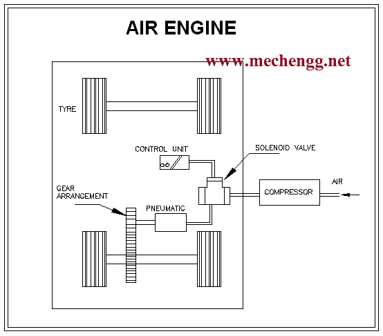
Air Engine Diagram
WORKING PRINCIPLE
In our project we operate the vehicle without using fuel. Inside the fuel we use compressed air supply, with gear arrangement. Here the vehicle consists of a gear arrangement, pneumatic gun, solenoid valve and control unit. In this, the vehicle's wheel axle is coupled to the spur gear and the pneumatic gun. Air from the compressor reaches the control unit and the air pressure is controlled and passes through the solenoid valve. The solenoid valve supplies the required amount of air to the pneumatic gun and the gun shaft fixes the gear that will rotate and the rotating gear is coupled with the wheel shaft gear to move the vehicle. Frozen air passes through the inlet port to rotate the pneumatic gun. Then the output shaft will be coupled to the rear drive using gear arrangements that are clearly shown in the diagram below.
O eletrodo 6013 é um dos tipos mais comuns e versáteis de eletrodos de soldagem utilizados na indústria e construção civil. Sua popularidade se deve às suas características únicas, que o tornam ide...
A escolha entre fundações profundas e rasas é uma decisão crucial no mundo da construção civil. Cada uma dessas opções apresenta vantagens e desvantagens específicas, e a seleção da mais adequada d...
O setor da construção civil enfrenta um desafio cada vez mais urgente: encontrar soluções sustentáveis que reduzam o impacto ambiental das obras e infraestruturas. Nesse contexto, o concreto geopol...
Cálculo de Rigidez Flexural em Barras de Aço
As estruturas metálicas são amplamente utilizadas em inúmeras aplicações, desde edifícios até máquinas e equipamentos. No entanto, a seleção adequada d...
Cálculo de Capacidade de Carga em Barras de Aço
As barras de aço são estruturas comuns em muitos tipos de edifícios, desde residências até grandes complexos industriais. No entanto, para garantir ...
Cálculo de Deflexão em Barras de Aço: Entendendo a Teoria
As estruturas em barras de aço são comuns em construções de todos os tipos, desde edifícios até pontes e túneis. No entanto, para que essa...
Em 2025, a confiança dos industriais brasileiros atingiu o menor patamar desde 2020, de acordo com uma pesquisa realizada pela Confederação Nacional da Indústria (CNI). Esse cenário reflete as ince...
O controle dos gastos públicos é um tema recorrente nas discussões sobre políticas econômicas. Embora muitas vezes visto como uma medida restritiva, essa abordagem pode trazer benefícios significat...

 Air Engine Diagram