With the advent of fiber laser technology, laser cutting machines have gained a significant position in the sheet metal processing industry.
During the processing of parts in laser cutting machines, high-temperature ablation leads to an increase in the production of smoke and dust, which can contaminate delicate parts of the equipment. Furthermore, smoke and dust also pose a threat to the health of operators.
Untreated cutting dust can significantly degrade the lifespan and cutting performance of laser cutting machines. Hence, the dust removal system is a crucial aspect of laser cutting machines.
The dust removal system of most laser cutting machines is designed as a comprehensive exhaust structure with a spacious cavity. To align with environmental protection requirements, it is necessary to use a high-power dust collector, which requires a large coverage area and complex piping installation.
The dust removal system design of laser cutting machines can easily lead to air opening and leakage, resulting in ineffective exhaust. During operation, the smoke and dust generated by the cutting process are not properly exhausted, affecting the operators' working environment.
One solution is to install a partition at the bottom of the laser cutting machine work table, dividing it into several longitudinal chambers of equal geometric dimensions with the main air suction duct located at the front. The main air suction duct is connected to the dust collector, and valves are placed between each chamber and the main air suction duct. The machine's control valve regulates the air flow through the air inlet and outlet tubes. A hopper is placed in a small room with end plates sealed at both ends and ventilation holes on the lower sides. The ventilation process is controlled by opening and closing valves, saving space and improving the dust removal effect.
Another solution includes the main body, main box and control cabinet. The dust removal cover absorbs all smoke and dust generated during the operation of the laser cutting machine, ensuring an unobstructed line of sight and greater work efficiency. It also prevents waste splashing, protects operators' safety, and increases the popularity and applicability of the device.
Although the dust removal system may not be the most important factor in selecting a laser cutting machine, an efficient dust removal system is crucial for normal production. In the current era of strict environmental protection regulations, devices with good environmental performance have a significant advantage.
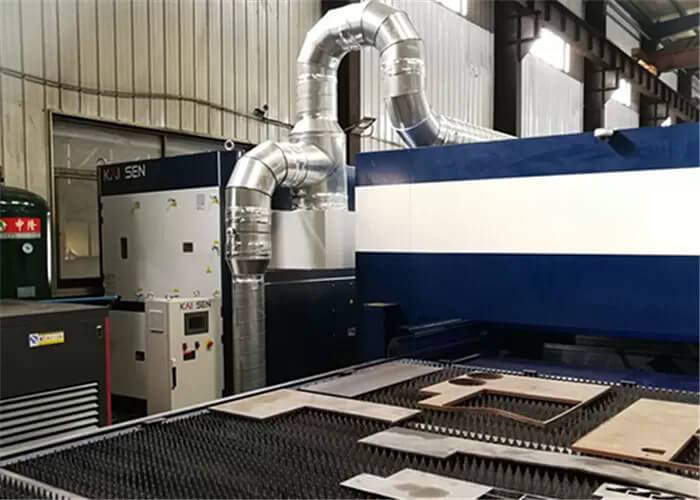
Fiber laser cutting machines do not produce large amounts of smoke and dust associated with traditional plasma cutting methods. The fiber optic laser cutting machine has a dedicated dust removal system that directly transports the collected smoke and dust to a filtration and purification unit before discharging it to meet environmental standards. The smoke and dust generated during the cutting process are mainly produced below the notch of the part. To save equipment investment and improve exhaust efficiency, only the cutting area is collected, with air outlet on the side of the fiber optic laser cutting machine. This framework is simple and effective and widely used.
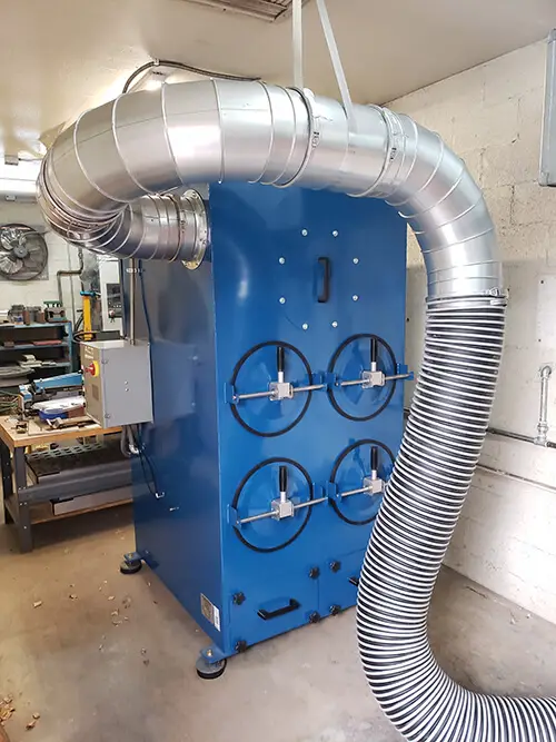
After carrying out extensive experiments, we have developed a dust collection system that effectively reduces smoke and dust during the laser processing process.
The system consists of an air purification dust collector that can effectively adsorb fine particles in the air stream. It is connected to the laser cutting machine via a 250mm diameter dust collection tube.
The dust collector extracts air from the laser cutting machine through the tube, filters and purifies it before discharging the clean air.
Despite the widespread availability of laser cutting machines with dust removal systems designed in accordance with the steps above, on-site use has revealed that these systems are not effective in removing smoke and dust generated during cutting.
Visible smoke and dust from cutting spread inside the equipment, affecting the precision transmission device and reducing the machining accuracy of the machine tool. The smoke can even spread throughout the workshop, threatening the health of users and polluting the environment.
The root cause of this problem is that although the dust collector extracts a significant amount of air from the machine tool, it cannot effectively remove the desired fumes and cutting dust.
Thus, despite the effort put into designing the dust suction tube in the machine tool, the performance of the dust removal system is inadequate due to design and processing/assembly issues. The result is a dust removal system that requires excessive effort for subpar results.
Methods to improve duct removal efficiency
Given the above facts, we have carried out several tests and identified the following methods that can effectively improve the dust removal efficiency of the system:
Improve the sealing performance of the dust removal system.
The dust collector provides a fixed suction air volume, so improving the sealing performance of the dust removal system will certainly increase the suction air volume of the specific suction outlet, thereby improving the dust removal efficiency of the system .
The dust collection system consists of the following components: an air purifying dust collector, a dust collection tube, the dust collection tube inside the machine tool, and air suction outlets with controllable opening and closing in each partition of the machine tool.
The main unsealed links that affect dust collection efficiency are the seal of the dust collection piping and the seal of each suction outlet.
At present, most of the air ducts on both sides of the machine body are integrated as part of the machine body through welding. However, this method poses a challenge to ensure complete welding between the tubes to prevent air leakage.
The sealing performance of the air suction outlet requires dividing the processing area into several zones based on the position of the laser head. For areas not processed by the laser head, the dust suction port must be sealed.
Reduce the right angle transition at the tube connection on the machine tool.
Taking a 3m x 1.5m processing format as an example, most manufacturers currently design their systems with tubes located under the side work tables on the left and right fuselages. This approach divides the air suction outlet into left and right sections along the Y direction, which theoretically improves dust suction efficiency, but also results in pipes connected at right angles to the fuselage.
These pipes connected at right angles impede air flow and weaken the wind force on the air suction outlet. Furthermore, when designing the fuselage, it is important to increase the cross-sectional area of the piping from the dust collector to the suction outlet inside the fuselage as much as possible.
A larger cross-section of piping reduces the resistance experienced by airflow and minimizes wind loss generated by the dust collector when it reaches the suction outlet.
Improve the sealing performance of the machine tool itself.
In theory, the final air extracted by the dust collector should come from inside the machine tool, but its dust collection efficiency is reduced due to the poor sealing performance of the machine tool itself.
In practical application, the smoke and dust produced during laser head processing originate from the bench plate. Under the influence of the high-energy laser beam, the metal vapor produced during processing condenses into small particles of metal powder when it encounters the surrounding cold air. These metallic dust particles are mainly concentrated near the countertop.
The objective is for the negative suction pressure generated by the suction outlet to remove these metal dust particles. However, the poor sealing performance of the machine tool itself leads to large gaps between the unloading truck and the machine body at the bottom of the machine tool and between the machine body and the ground. In addition, the suction port is close to the ground and the unloading truck, which causes most of the suction air to enter the machine tool through the space between the machine body and the ground and be transported to the Air purification dust collector by suction system. .
This causes the suction system to perform unnecessary work.
Do a good job on the shield and top cover of the machine tool.
The top cover of the machine tool is an important component of the dust collection system. Laser head processing requires cutting gas.
A portion of the cutting gas will mix with the metal dust and spread into the overhead space above the bench, which is normally not easily removed by the dust collection system.
In this case, the top cover of the machine tool will retain the dust inside the machine tool, and then, under the influence of gravity, this part of the dust will eventually be removed from the machine tool by the dust suction system.
Conclusion
Implementing these design ideas can significantly increase the dust collection efficiency of laser cutting machine tools.
Our machine tools not only add value to customers, but also align with the principles of green and sustainable development.