
Flame cutting accuracy refers to the error ratio between the geometry of the cut part and its design size. The quality of flame cutting, on the other hand, is determined by several factors, such as the surface roughness of the cut section, the degree of melting and collapse of the upper edge of the cut, the presence of slag on the lower edge, and the uniformity of the width. cutting. Flame cutting accuracy is maintained through proper control of process parameters.
The following factors play a crucial role in determining flame cutting quality:
- Type of fuel gas used
- Cutting torch type
- Oxygen purity, pressure, flow rate and flow shape used for cutting
- Cutting speed and tilt angle
- Flame adjustment
- Preheat flame energy rate
- Angle of inclination between the cutting nozzle and the workpiece and the distance of the cutting nozzle from the surface of the workpiece.
Cutting oxygen flow plays a key role in flame cutting. It not only ignites the metal, but also removes oxides generated by combustion from the cut. Consequently, the purity, flow rate and shape of the cutting oxygen flow have a significant impact on both flame cutting quality and cutting speed.
Type of fuel gas
In flame cutting, various flammable gases such as acetylene, propane, natural gas and MAPP (methane + ethane + propane) are commonly used. Gases with high burning value and fast burning speed are normally preferred for cutting thin sheets, while gases with low burning value and slow burning speed are more suitable for cutting thicker sheets. For steel sheets thicker than 200 mm, natural gas is ideal for achieving high cutting quality, although it may result in a slightly reduced cutting speed.
Compared to natural gas, acetylene is significantly more expensive. However, due to resource constraints, acetylene is typically used in production. Natural gas is only considered when cutting large and thick sheets that require high cutting quality and abundant resources.
Torch type
The thicker the piece to be cut, the higher the type of torch, number of nozzles and oxygen pressure must be. The relationship between oxygen pressure, thickness of the cut piece, type of torch and number of nozzles is demonstrated in the corresponding table.
| Nozzle specification. |
Nozzle throat diameter mm |
Cutting thickness mm |
Cutting speed MPa |
Gas pressure |
Incision mm |
||
|---|---|---|---|---|---|---|---|
| mm/min | Oxygen | Acetylene | Liquefied petroleum gas | ||||
| 1 | 0.6 | 5-10 | 750-600 | 0.7 | 0.025 | 0.03 | ≤1 |
| two | 0.8 | 10-20 | 600-450 | 0.7 | 0.025 | 0.03 | ≤1.5 |
| 3 | 1 | 20-40 | 450-380 | 0.7 | 0.025 | 0.03 | ≤2 |
| 4 | 1.25 | 40-60 | 380-320 | 0.7 | 0.03 | 0.035 | ≤2.3 |
| 5 | 1.5 | 60-100 | 320-250 | 0.7 | 0.03 | 0.035 | ≤3.4 |
| 6 | 1.75 | 100-150 | 250-160 | 0.7 | 0.035 | 0.04 | ≤4 |
| 7 | two | 150-180 | 160-130 | 0.7 | 0.035 | 0.04 | ≤4.5 |
| 1A | 0.6 | 5-10 | 560-450 | 0.5 | 0.025 | 0.03 | ≤1 |
| 2A | 0.8 | 10-20 | 450-340 | 0.5 | 0.025 | 0.03 | ≤1.5 |
| 3A | 1 | 20-40 | 340-250 | 0.5 | 0.025 | 0.03 | ≤2 |
| 4A | 1.25 | 40-60 | 250-210 | 0.5 | 0.03 | 0.035 | ≤2.3 |
| 5A | 1.5 | 60-100 | 210-180 | 0.5 | 0.03 | 0.035 | ≤3.4 |
Cutting oxygen purity, pressure, flow rate, oxygen flow shape
Reducing oxygen purity
Oxygen purity also has a significant impact on oxygen consumption, cut quality and cutting speed. If the purity of oxygen decreases, impurities such as nitrogen will absorb heat during the cutting process and form a gas film on the cutting surface, preventing the metal from burning and slowing the oxidation process. This results in a drastic reduction in cutting speed, a wider kerf, a rougher cutting surface, slag on the lower edge of the kerf and an increase in oxygen consumption.
The following graph illustrates the influence of oxygen purity on cutting time and oxygen consumption. The vertical axis represents cutting time (1) and oxygen consumption (2).
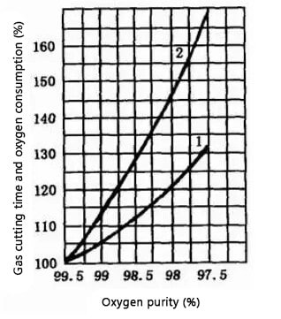
A decrease in oxygen purity from 97.5% to 99.5% results in a 10% to 15% increase in cutting time and a 25% to 35% increase in oxygen consumption for every 1% decrease in oxygen purity. purity for a 1 meter long cut. Therefore, it is crucial to maintain the highest possible oxygen purity, generally above 99.5%. A purity of less than 95% makes the cutting process very difficult.
To achieve slag-free cutting in gas cutting, the oxygen purity must be at least 99.6%. Although using liquid oxygen cutting requires a high initial investment, it has much better overall economic performance in the long term.
Reducing oxygen pressure
When cutting thin parts, the cutting oxygen pressure can be reduced appropriately. However, it is important to avoid making the pressure too low or too high. If the pressure is too high, it will result in a wider cutting seam, reduced cutting speed, rough cutting surface and strong cooling effect on the cut parts.
On the other hand, if the pressure is too low, it will slow down the oxidation reaction during the cutting process, resulting in a slag bond at the back of the cut that is difficult to remove and potentially preventing the cut from being completed.
As the cutting oxygen pressure increases, the oxygen flow rate also increases, allowing thicker plates to be cut. However, there is a maximum thickness that can be cut, beyond which increasing pressure will not result in an increase in cuttable thickness. The effect of cutting oxygen pressure on cutting speed is similar.
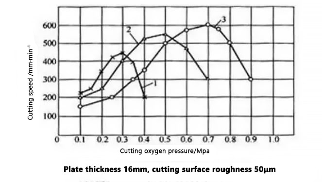
The influence of cutting oxygen pressure on cutting speed
As shown in the figure, when using a common gas cutting nozzle, the cutting speed increases with pressure at low pressure levels. However, when the pressure exceeds 0.3 MP, the cutting speed decreases and the cutting speed increases, resulting in a rough cutting cross section.
On the other hand, when using a diffusion-shaped nozzle for gas cutting, if the cutting oxygen pressure matches the design pressure of the nozzle, the cutting speed increases with increasing pressure. This is because the flow rate and thrust of the cutting oxygen flow increases, resulting in a higher cutting speed compared to using a regular nozzle.
Recommended oxygen pressure cut-off value
| Thk./mm | Reducing oxygen pressure /MPa |
|---|---|
| 3-12 | 0.4-0.5 |
| 12-30 | 0.5-0.6 |
| 30-50 | 0.5-0.7 |
| 50-100 | 0.6-0.8 |
| 100-150 | 1.0-1.4 |
In practical cutting work, the best cutting oxygen pressure can be determined through the “wind line” test method. For a given nozzle, the appropriate pressure is when the wind line is clearest and longest, resulting in the best cutting result.
Cutting off the flow of oxygen
The figure illustrates the effect of oxygen flow rate on cutting speed when cutting a 12 mm thick steel plate. As shown in the figure, the cutting speed gradually increases with increasing oxygen flow rate, but beyond a certain threshold value, it decreases.
This means that there is an ideal oxygen flow rate for a specific thickness of steel sheet that results in not only the highest cutting speed, but also the best cut quality.
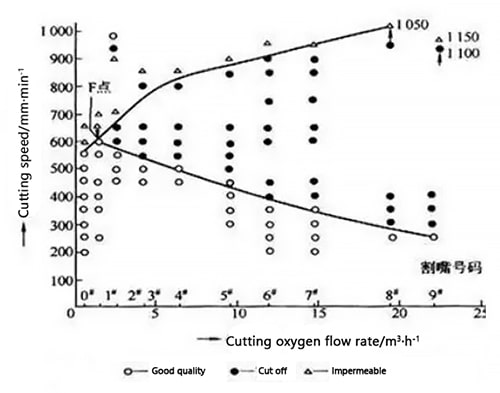
The influence of oxygen flow rate on cutting speed (plate thickness 12 mm)
Cutting speed, inclined cutting speed, inclination angle
Cutting speed
Cutting speed depends on the thickness of the part and the shape of the cutting nozzle, typically decreasing as the thickness of the part increases. The cutting speed must be adjusted to match the oxidation rate of the metal in the cut.
The cutting speed directly influences the stability of the cutting process and the quality of the cut section. Trying to artificially adjust the cutting speed to improve productivity or slow it down to improve the quality of the cut section will not work and will instead result in a deterioration in the quality of the cut section.
Too slow a cutting speed will reduce productivity by causing the top edge of the cut to crumble and melt, the bottom edge to have rounded corners, and the bottom of the cut section to have deep grooves for water washing. On the other hand, too fast a cutting speed will result in excessive drag, causing the cutting section to have depressions and suspended slag and, in severe cases, even prevent the cutting from being completed.
Compared to manual cutting, mechanized cutting presents an average increase of 20% in cutting speed. The following table lists recommended cutting speeds for mechanized cutting.
Recommended data for cutting speed during mechanical cutting
| Steel Thk. | Cutting shape | ||||
|---|---|---|---|---|---|
| Straight cut of semi-product | Organic processing subsidy cut | Cutting with low surface cut quality requirements | Precise straight cut | Precise formation cutting | |
| 5 | / | 330-350 | 710-760 | 590-640 | 400-500 |
| 10 | 710-730 | 330-470 | 570-620 | 480-520 | 320-400 |
| 20 | 580-630 | 400 | 470-500 | 390-420 | 260-330 |
| 30 | 520-560 | 350 | 410-450 | 350-380 | 230-290 |
| 50 | 440-480 | 330 | 350-380 | 300-320 | 200-250 |
| 100 | 380-420 | 290 | 310-330 | 260-280 | 170-220 |
| 150 | 360-390 | 260 | 290-310 | 240-260 | 160-200 |
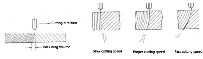
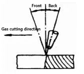
Proper cutting speed can be determined by observing the characteristics of the slag ejected from the cut. In normal flame cutting, the cutting oxygen flow is slightly inclined relative to the vertical torch, and this displacement is called the backward drag amount (as shown in the figure).
The cutting speed can be determined based on the direction of the slag sparks falling into the cut. When the speed is very low and there is no backward drag, the spark beam below the workpiece is displaced in the cutting direction. Increasing the torch operating speed will shift the spark beam in the opposite direction. When the spark beam is parallel to the cutting oxygen flow or slightly ahead of the discharge, the cutting speed is considered normal. However, if the speed is too high, the spark beam will obviously be behind.
Cutting inclination
The angle of inclination between the cutting nozzle and the workpiece directly affects the gas cutting speed and the amount of back drag. The size of the cutting slope is mainly determined by the thickness of the part.
For steel sheets less than 4 mm thick, the cutting nozzle should be tilted back at an angle of 25° to 45°. When cutting steel sheets with a thickness of 4 to 20 mm, the nozzle must be tilted back at an angle of 20° to 30°. For steel sheets with a thickness of 20 to 30mm, the cutting nozzle must be perpendicular to the part. For parts thicker than 30 mm, the cutting nozzle must be tilted forward at an angle of 5° to 10° at the beginning of cutting and 5° to 10° after cutting. For manual curved cutting, the cutting nozzle must be perpendicular to the workpiece.
The relationship between the nozzle cutting slope and the cutting thickness is shown in the figure.
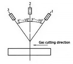
- 1-Thickness <6mm
- 2- The thickness is 6-30 mm
- 3- Thickness > 30mm
The angle of inclination between the cutting nozzle and the workpiece has a direct effect on the gas cutting speed and the amount of back drag. If the angle is not chosen correctly, not only will it not improve the gas cutting speed, but it will also increase oxygen consumption and even cause difficulties in gas cutting.
Flame adjustment
By adjusting the proportion of oxygen and acetylene, three types of cutting flames can be produced: neutral flame (also known as normal flame), oxidizing flame and reducing flame (as shown in the figure below).
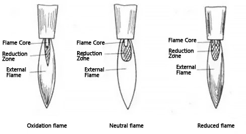
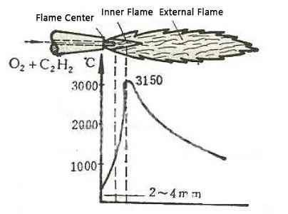
The normal flame is characterized by the absence of free oxygen and reactive carbon in its reduction zone, and has three distinct areas with a well-defined flame core (which is almost cylindrical). The flame core consists of acetylene and oxygen and has a uniformly rounded, glowing shell at its end. The outer layer is made up of incandescent carbonaceous tips and the temperature of the flame core reaches 1000°C.
The reduction zone is located outside the flame core and has a darker glow compared to the flame core. It is composed of the products of incomplete combustion of acetylene – carbon dioxide and hydrogen, and its temperature can reach around 3,000°C.
The outer flame, or zone of complete combustion, is located outside the reduction zone and consists of carbon dioxide and water vapor, nitrogen. Its temperature varies between 1200°C and 2500°C.
The oxidizing flame is produced in the presence of excess oxygen, and its flame core is conical, shortened in length, with an unclear outline and opaque brightness. The reduction zone and outer flame are also shortened, and the flame is blue-violet, burning with a loud sound. The size of the sound is related to the oxygen pressure, and the temperature of the oxidizing flame is higher than that of the normal flame. If used for cutting, it will significantly reduce the cutting quality.
The reducing flame is produced in the case of excess acetylene and its flame core does not have a clear contour. The end of the flame core has a green border, which is used to determine the presence of excess acetylene. The reduction zone is extraordinarily bright and almost blends with the core of the flame. The external flame is yellow in color. If there is too much excess acetylene, it will begin to produce black smoke due to the lack of oxygen necessary for the combustion of acetylene in the flame.
The size of the energy in the preheating flame is closely related to the cutting speed and cutting quality.
In the process of cutting a steel plate, the strength of the preheating flame must be adjusted according to the thickness of the workpiece and the cutting speed. As the thickness of the workpiece increases and the cutting speed increases, the flame energy must be increased, but not too strong. Excessively strong preheating flames can cause serious collapse by melting the upper edge of the incision.
On the other hand, if the preheating flame is too weak, the steel sheet will not receive enough energy, requiring a reduction in cutting speed and even interruptions in the cutting process.
Therefore, the relationship between preheating flame strength and cutting speed is interdependent. For cutting steel sheets with a thickness of less than 200mm, a neutral flame is recommended for better cutting quality.
When cutting thick steel sheets, a reducing flame must be used to preheat the cut, with the length of the flame being at least 1.2 times greater than the thickness of the sheet.
Preheat flame energy rate
The preheating flame plays a crucial role in gas cutting, heating the metal workpiece to ignition temperature and maintaining that temperature. The purpose of the preheating flame is to facilitate the cutting process by removing and melting the oxide layer on the surface of the steel, allowing the cutting oxygen flow to come into contact with the metal.
The choice of preheating flame, whether neutral or slightly oxidizing, is a crucial process parameter that affects the quality of gas cutting. The use of a carbonization flame is not recommended as it may char the edge of the cut. The intensity of the preheating flame should be moderate and selected based on the thickness of the part, the type of cutting nozzle and quality requirements.
When cutting thick steel sheets, the flame energy rate must be reduced to prevent the upper edge of the cut from melting.
On the other hand, when cutting thin steel sheets, the flame energy rate can be increased, but the cutting nozzle must be kept a certain distance from the workpiece and maintain a certain inclination angle.
If the preheat flame energy rate is too low when cutting thin steel sheets, the workpiece will not receive enough heat, causing a reduction in gas cutting speed or even interruptions in the cutting process.
- The strength of the preheating flame must be increased as the thickness of the part to be cut increases. The thicker the workpiece, the greater the strength of the preheating flame.
The relationship between the power of the oxygen-acetylene preheating flame and the thickness of the plate
| Thk./mm | Flame power /L.Min -1 |
|---|---|
| 3-25 | 4-8.3 |
| 25-50 | 9.2-12.5 |
| 50-100 | 12.5-16.7 |
| 100-200 | 16.7-20 |
| 200-300 | 20-21.7 |
- When cutting thicker steel plates, a light carbide flame should be used to prevent the upper edge of the cut from collapsing and also to make the outer flame longer.
- When using diffusion type nozzle and oxygen curtain nozzle to cut steel sheets below 200mm thickness, the flame power should be higher to accelerate the heating of the leading edge of the cut to the ignition point, so as to obtain a higher cutting speed.
- When cutting steels with a higher carbon content or alloy elements, as they have a higher ignition point, the preheating power of the flame must be greater.
- When cutting chamfers with a single cutting nozzle, because the slag is blown out of the cut, to increase the flame power and obtain additional energy.
The preheating time for gas flame cutting must be determined based on the thickness of the part to be cut. The following is a list of empirical data for the selected preheating time in gas flame cutting.
Empirical data on selected preheating time for gas flame cutting
| Thk./mm | Preheating time/S | Thk./mm | Preheating time/S |
|---|---|---|---|
| 20 | 6-7 | 150 | 25-28 |
| 50 | 9-10 | 200 | 30-35 |
| 100 | 15-17 |
Angle of inclination between the cutting nozzle and the workpiece and distance from the workpiece surface
The distance between the cutting nozzle and the surface of the part is crucial in determining the quality of the cut. The ideal distance depends on the thickness of the part and the length of the preheating flame.
If the cutting nozzle is too close to the workpiece, it may cause melt collapse at the upper edge of the cut, block the cutting nozzle with spatter, and even cause tempering. On the other hand, if the height of the cutting nozzle is too high, heat loss increases and the effectiveness of the preheating flame at the front edge of the cut decreases, leading to insufficient preheating and decreased flow energy. of cutting oxygen, making it difficult to remove slag and affecting the quality of the cut. Oxygen purity in cutting is also reduced, resulting in an increase in the amount of back drag and cutting width, as well as a reduction in cutting speed for thin sheets.
Typically, the flame core should be kept 3-5 mm from the surface of the workpiece to obtain the best heating conditions and minimize the risk of carburization. If the flame core touches the surface of the workpiece, it will not only melt the top edge of the cut, but also increase the risk of carburization in the cut.
The distance between the cutting nozzle and the surface of the part must be adjusted according to the thickness of the part to be cut.
When cutting thin sheets, the cutting speed is faster and the flame can be larger, so the distance between the cutting nozzle and the workpiece surface can be larger.
On the other hand, when cutting thick plates, the cutting speed is slower, therefore, to avoid melting the upper edge of the cut, the preheating flame should be smaller and the distance between the cutting nozzle and the cutting surface piece must be smaller. This allows you to maintain the straightness of the cutting oxygen flow and the purity of the oxygen, improving the quality of the cut.
Best Parameters of CNC Flame Cutting Machine for Low Carbon Steel Sheet Cutting (GK1 Rapid Cutting Nozzle)
| Cut Thk./mm | 25 | 30 | 35 | 40 | 45 | 50 | 60 | 70 | 80 | 90 | 100 | 150 | 200 | 300 |
|---|---|---|---|---|---|---|---|---|---|---|---|---|---|---|
| No mouthpiece. | 3 | 3 | 3 | 4 | 4 | 4 | 4 | 5 | 5 | 5 | 5 | 6 | 7 | 9 |
| Cut height /mm |
3.5 | 3.5 | 3.5 | 4 | 4 | 4 | 5 | 5 | 6 | 6 | 7 | 7 | 8 | 10 |
| Cut oxygen pressure /MPa |
0.5 | 0.6 | 0.6 | 0.6 | 0.6 | 0.6 | 0.65 | 0.65 | 0.65 | 0.7 | 0.7 | 0.8 | 1 | 1.2 |
| Cut acetylene pressure /Mpa |
0.05 | 0.06 | 0.06 | 0.06 | 0.06 | 0.06 | 0.07 | 0.07 | 0.07 | 0.07 | 0.07 | 0.08 | 0.1 | 0.1 |
| Cut speed /mm·min-1 |
400 | 380 | 350 | 350 | 330 | 320 | 300 | 250 | 250 | 250 | 220 | 220 | 200 | 120 |
| Preheat time /s |
6 | 7 | 7 | 8 | 8 | 8 | 10 | 10 | 10 | 15 | 15 | 28 | 35 | 40 |
| Flame power /L.min |
9~13 | 13~22 | ||||||||||||


