1. What is a gear?
A gear is a toothed mechanical component that can mesh with other gears. Its application in mechanical transmission and the entire mechanical field is extremely extensive.
2. The history of gears
As early as 350 BC, the famous Greek philosopher Aristotle recorded about gears in his literature.
Around 250 BC, mathematician Archimedes also described the use of a turbine and helical gear in a hoist in his literature.
Gears from centuries before Christ are still preserved in the Ktesibios water clock in Iraq.

The history of gears in China dates back to ancient times and has a long and extensive history. According to historical records, gears were used as early as 400-200 BC in ancient China.
The bronze gears excavated in Shanxi province are the oldest gears discovered so far in the world. The guided cars that reflected the achievements of ancient science and technology were mechanical devices that revolved around gear mechanisms.
During the Italian Renaissance in the second half of the 15th century, the famous genius Leonardo da Vinci not only left an indelible mark on cultural and artistic aspects, but also made significant contributions to the history of gear technology.
After more than 500 years, today's gears still retain the prototype sketches from that time.
(1) Spur gear

(2) Rack and pinion

(3) Helical Gear with Crossed Shafts

(4) Bevel Gear

(5) High transmission rate hypoid bevel gear

(6) Worm gear
It wasn't until the late 17th century that people began to study the shape of the wheel's teeth, which could transmit movement accurately. After the Industrial Revolution in Europe in the 18th century, the application of gear transmission became increasingly widespread.
First the cycloidal gear was developed, followed by the involute gear. In the early 20th century, involute gearing became dominant in its application. Later, gears such as helical gear, arc gear, bevel gear and inclined gear were developed.
Today, modern gear technology has made great strides. Gear modules range from 0.004 to 100 millimeters, gear diameter can vary from 1 millimeter to 150 meters. The power transmission capacity can reach up to 100,000 kilowatts and the rotation speed can reach 100,000 revolutions per minute. The highest circumferential speed can reach up to 300 meters per second.
Internationally, power transmission devices are developing toward miniaturization, high speed and standardization. Some trends in gear design include the application of specialty gears, the development of planetary gear devices, and the research and development of low-vibration, low-noise gear systems.
3. Gears are generally divided into three main categories.
There are several types of gears and the most common classification method is based on the gear shaft.
Generally, gears are classified into three types: parallel axis, intersecting axis and inclined axis.
Parallel shaft gears: including spur gears, helical gears, internal gears, racks and helical racks.
EU Intersecting shaft gears: including straight bevel gears, spiral bevel gears, zero degree bevel gears, etc.
Inclined shaft gears: including helical gears with crossed shafts, helical gears, hypoid bevel gears, etc.
| Gear transmission type | Kind of equipment | Transmission efficiency (%) | 3D Graphic Representation |
Parallel axis 
|
spur gears | 98.0-99.5 |

|
| Helical gears |

|
||
| Racks, helical racks |

|
||
| Internal gears |

|
||
Intersection axis 
|
Miter Gears | 98.0-99.0 |

|
| Straight bevel gears |

|
||
| Spiral bevel gears |

|
||
Inclined axis 
|
Screw Gears | 70.0-95.0 |

|
| Worms | 30.0-90.0 |

|
|
| Worm wheels |
|
The efficiency listed in the table above is the transmission efficiency, which does not include losses in bearings and agitation lubrication. The meshing of parallel-axis and cross-axis gear pairs is basically rolling, and the relative slip is very small, so the efficiency is high.
The meshing of stepped shaft gear pairs such as helical gears and helical gears has a significant impact on friction because they achieve power transmission through relative slip, causing a reduction in transmission efficiency compared to other gears.
Gear efficiency refers to the transmission efficiency of gears in their normal assembled condition.
If there is improper installation, especially when the mounting distance of the bevel gear is incorrect and causes error in the intersection of the same bevel, its efficiency will decrease significantly.
3.1 Parallel axis gears
1. Spur gears
Cylindrical gears for which the tooth lines and axial lines are parallel. They are widely used in power transmission because they are easy to process.

2. Rack
A spur gear that meshes with spur gears. It can be seen as a special case where the pitch diameter of the spur gear becomes infinitely large.

3. Internal gears
Gears with machined teeth on the inside of a ring that mesh with spur gears. They are mainly used in applications such as planetary gear transmission mechanisms and gear couplings.

4. Helical gears
Cylindrical gears with rows of helix-shaped teeth. They are widely used due to their high strength and smooth operation compared to spur gears. They generate axial thrust during transmission.
5. Helical Rack
A rack gear that meshes with helical gears. It is equivalent to the case where the pitch diameter of the helical gear becomes infinitely large.

6. Herringbone gears
Gears consisting of two helical gears with opposite helix angles. They have the advantage of not generating axial thrust.

3.2 Intersecting axis gears
1. Straight bevel gears
Bevel gears with rows of teeth parallel to the cone generatrix. They are relatively easy to manufacture compared to other types of bevel gears.
Therefore, they are widely used in bevel gear applications for power transmission.

2. Spiral bevel gears
Bevel gears with curved tooth lines and helix angle. Although they are more difficult to manufacture than straight bevel gears, they are widely used as high-strength, low-noise gears.

3. Zero bevel gears
Curved bevel gears with zero degree helix angle. They have the characteristics of straight and spiral bevel gears, with the tooth surface subjected to the same force situation as straight bevel gears.

3.3 Stepped Shaft Gears
1. Pair of helical gears
The term “worm gear pair” refers to a combination of a worm and a worm wheel that meshes with it. The greatest feature of the helical gear pair is that a large gear ratio can be obtained with just one pair and they operate silently. However, its low efficiency is a disadvantage.

2. Pair of worm gear and helical gear
Term used when pairs of cylindrical helical gears are used for transmission between stepped shafts. They can be used in the case of helical gear pairs or between helical and spur gear pairs. Although they run smoothly, they are only suitable for use under light loads.

3.4 Other Special Gears
1. Face Gears
Disc-shaped gears that can mesh with spur gears or helical gears. They are used for transmission between orthogonal axles and stepped axles.

2. Pair of hourglass worm gear
The term “hourglass helical gear pair” refers to a combination of an hourglass helical wheel and a helical wheel that meshes with it. Although they are more difficult to manufacture compared to cylindrical helical gear pairs, they can transmit heavy loads.

3. Hypoid Gears
Bevel gears used for transmission between stepped axles. The larger and smaller gears are machined eccentrically, similar to the case of spiral bevel gears. The mesh principle is very complex.

4. Basic Terminology and Calculations Gear Dimensions
Gears has distinct terminology and presentation methods. In order to improve the understanding of gears, here are some commonly used basic gear terminologies.
1. Names of gear parts

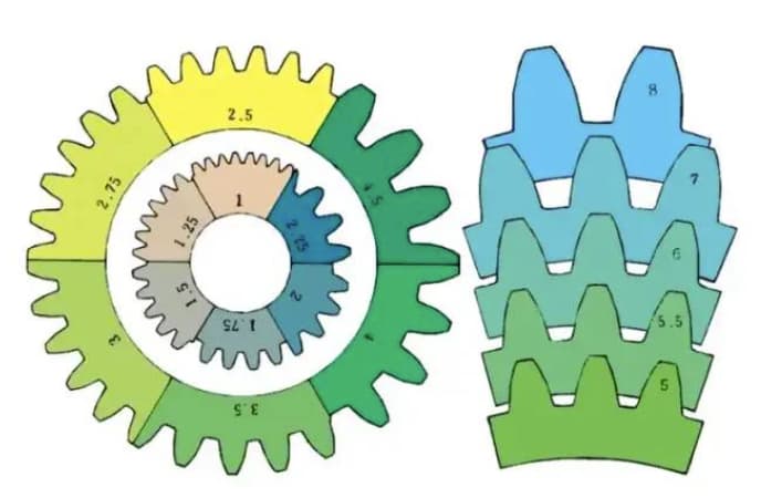
2. The term used to indicate the size of a gear is called modulus
m1, m3, m8… are known as module 1, module 3, module 8 respectively. The module is universally used throughout the world to indicate gear size, using the symbol m (modulus) and numbers (millimeters) to represent the size of the teeth.
The higher the number, the bigger the gear.
In countries that use imperial units, such as the United States, tooth size is indicated by the symbol DP (diametric pitch) and numbers (number of teeth for a gear with a pitch diameter of 1 inch).
For example: DP24, DP8 etc. There is also a comparison and a special method to indicate the size of the teeth using the symbol CP (circular pitch) and numbers (millimeters) such as CP5, CP10.
The step (p) can be obtained by multiplying the module by pi. Pitch is the length between adjacent teeth.
The formula is: p = pi xm
Tooth size comparison for different modules:
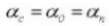
3. Pressure angle
The pressure angle is a parameter that determines the shape of the gear teeth. It refers to the surface inclination of the gear teeth and is usually set at 20 degrees (α).
Previously, gears with a pressure angle of 14.5 degrees were common.
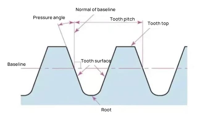
The pressure angle is the angle formed between the radius and the tangent of the tooth shape at a specific point on the tooth surface (usually the node). As shown in the image, α is the pressure angle. α' is also a pressure angle, since α' = α.


When the mesh state of gear A and gear B is viewed from the node, gear A pushes gear B from the node. At this time, the driving force acts on the common normal of Gear A and Gear B. In other words, the common normal is the direction of force and the direction of pressure, with α being the pressure angle.
The module (m), the pressure angle (α) and the number of teeth (z) are the three basic parameters of a gear. On this basis, each part of the gear is calculated in terms of size.
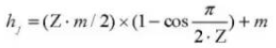
4. Addendum and Dedendum
The height of a gear tooth is determined by the module (m).

The total height of the tooth is h=2.25m (= addendum height + dedendum height).
Addendum height (ha) is the height from the tip of the gear tooth to the pitch circle. ha=1m.
The dedendum height (hf) is the height from the root of the gear tooth to the pitch circle. heart rate=1.25m.
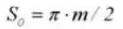
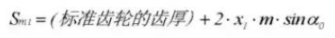
The reference for the thickness of the gear tooth(s) is half pitch. s=πm/2.
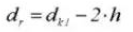
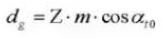
5. Gear diameter
The parameter that determines the size of a gear is the diameter of the pitch circle (d). Based on the pitch circle, the pitch, thickness, height, addendum height and dedendum height of the gear can be determined.
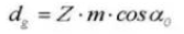
The diameter of the pitch circle is d = zm.
The diameter of the additional circle is da=d+2m.
The diameter of the dedendum circle is df=d-2.5m.
The pitch circle cannot be directly seen on the actual gear because it is an assumed circle used to determine the size of the gear.

6. Center distance and clearance
When the pitch circles of a pair of gears mesh tangentially, the center distance is half the sum of the diameters of the pitch circles.
Center distance a=(d1+d2)/2

Backlash is an important factor in achieving smooth engagement of gears during engagement. It is the space between the tooth surfaces when a pair of gears are in mesh.
There is also play in the direction of the gear tooth height. This clearance is known as axial clearance or backlash (c). Backlash (c) is the difference between the diameter of the root circle of a gear and the diameter of the tip circle of its corresponding gear.
Clearance c=1.25m-1m=0.25m

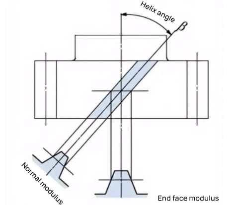
7. Helical gear
A gear whose teeth are twisted spirally after a spur gear is called a helical gear. Most geometric calculations for a spur gear are applicable to a helical gear. There are two types of helical gears based on their reference surfaces:
- End face reference (perpendicular to axis) (end face modulus/pressure angle)
- Flank reference (perpendicular tooth) (normal modulus/pressure angle)
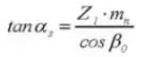
- The formula for the relationship between the end face modulus (mt) and the normal modulus (mn) is mt=mn/cosβ.
8. Propeller direction and mesh
For helical gears, such as helical gears and cycloidal gears, whose teeth are helical in shape, the direction of the helix and the meshing are fixed.
Propeller direction refers to when the gear shaft points up and down, the direction of the teeth is toward the top right as “right” and toward the top left as “left” when viewed from the front. The meshing of various types of gears is shown below.

5. The most commonly used tooth profile for gears is the involute tooth profile.
If equally spaced teeth are only partitioned on the outer periphery of the friction wheel, fitted with projections, and then mesh and rotated with each other, the following problems may arise:
When gear transmission needs to be quiet and smooth, involute curves are used.
1. What is an involute curve?
An involute curve is a curve obtained by wrapping a wire with a pencil around the outer periphery of a cylinder and gradually releasing the wire into a taut state.
The curve drawn by the pencil is the involute curve, and the outer periphery of the cylinder is called the base circle.

2. An example of an 8-tooth involute gear
Divide the cylinder into 8 equal parts and tie 8 pencils to them to draw 8 enclosing curves. Then wrap the strands in the opposite direction and draw 8 more curves using the same method. This is an 8-tooth gear with involute curves as the tooth profile.

3. Advantages of involute gears
The advantages of involute gears include their ability to transmit a constant speed ratio, smooth operation due to their gradually changing contact pattern, and low sensitivity to center distance variations.
4. Base Circle and Fundamental Circle
The base circle is the fundamental circle that forms the surrounding profile of the tooth. The pitch circle is the reference circle that determines the size of the gear. The base circle and pitch circle are important geometric dimensions of gears.
The tooth involute profile is a curve formed on the outside of the base circle, and the pressure angle on the base circle is zero.
5. Involute gear gear
When two standard involute gears are meshed, their pitch circles are tangent to each other at the standard center distance. The appearance of the meshing of the two gears resembles the transmission of two friction wheels with diameters d1 and d2, respectively.
However, the meshing of the involute gears actually depends on the base circle and not the pitch circle.

The contact points between the meshing teeth of two gears move along the line of action in the sequence of P1, P2 and P3.
Pay attention to the yellow tooth on the drive gear. After this tooth begins to mesh, the gear is in a state of two-tooth meshing (P1, P3) for a period of time. The mesh continues and when the contact point moves to point P2 on the pitch circle, only one tooth remains on the mesh.
The meshing continues, and when the contact point moves to point P3, the next gear tooth begins to mesh with point P1, again forming a two-tooth meshing state. In this way, the two-tooth meshing and the one-tooth meshing of the gears interact and transmit rotational motion repeatedly.
The common tangent line between the base circles, AB, is called the line of action. The contact points of the gear pairs are all on this line of action.

With an illustrative diagram, it is like a belt that runs on the outer peripheries of two basic circles and transmits energy through rotational movement.

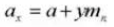
6. Gear displacement is divided into positive displacement and negative displacement.
The gear tooth profile we usually use is generally a standard involute, but there are also situations where the gear teeth need to be shifted, such as adjusting the center distance or avoiding the undercut of the smaller gear.
1. Number and shape of gear teeth
The involute curve of the tooth shape varies with the number of teeth. The more teeth there are, the more the tooth shape curve tends towards a straight line.
As the number of teeth increases, the shape of the tooth root becomes thicker and the strength of the sprocket increases.
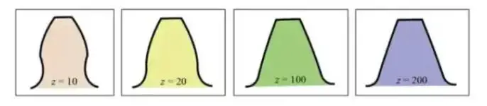
In the graph above, it can be seen that for a gear with 10 teeth, part of the tooth involute profile at the tooth root is removed, resulting in undercutting.
However, by adopting a positive displacement for the gear with z = 10, increasing the diameter of the addendum circle and increasing the thickness of the gear teeth, the same gear strength of a gear with 200 teeth can be obtained.
2. Shifted gears
The following diagram shows the schematic diagram of a 10-tooth gear with positive displacement. During gear cutting, the amount of movement of the tool along the radial direction is called the radial displacement amount (referred to as displacement amount) xm(mm).
- xm = Amount of displacement (mm)
- x = Displacement coefficient
- m = Module (mm)

Through the positive displacement of the tooth profile, the gear tooth thickness increases and the outer diameter (additional circle diameter) also increases.
By adopting positive displacement, gear reduction can be avoided. Shifting gears can also achieve other purposes, such as changing center distance. Positive offset can increase the center distance, while negative offset can reduce it.
Regardless of whether it is a gear with positive or negative displacement, there are limitations regarding the value of the displacement.
3. Positive and Negative Displacement
The displacement can be positive or negative. Although the height of the tooth is the same, the thickness of the tooth is different. A gear with thickened tooth thickness is a positive displacement gear, while a gear with reduced tooth thickness is a negative displacement gear.

When it is not possible to change the center distance between two gears, a positive shift can be applied to the smaller gear (to avoid undercutting) and a negative shift can be applied to the larger gear in order to obtain the same center distance. In this case, the absolute value of the displacement value is equal.

4. Shift gear gear
Standard gears mesh when their pitch circles are tangent to each other. The meshing of the offset gears, as shown in the figure, is tangent to each other on the meshing circle.
The pressure angle on the mesh circle is called the mesh angle. The meshing angle is different from the pressure angle on the pitch circle (pitch circle pressure angle) and is an important factor in the design of offset gears.

5. Gear shift function
Gear shifting can avoid cuts caused by a small number of teeth during machining. The desired center distance can be obtained by offset.
In a pair of gears with a large difference in the number of teeth, positive shift can be applied to the easily worn smaller gear to increase tooth thickness, while negative shift can be applied to the larger gear to reduce tooth thickness, the order to make the life expectancy of the two gears more comparable.
7. Gear Accuracy
Gears are mechanical components that transmit power and rotation. The main requirements for gear performance are:
To meet the above requirements, improving gear precision will become a necessary task.
1. Gear Accuracy Classification
Gear accuracy can be divided into three categories:
a) Tooth involute profile accuracy – tooth profile accuracy
b) Accuracy of the tooth flank line on the tooth surface – tooth line accuracy
c) Accuracy of the position of the teeth/grooves.

2. Tooth profile error
Tooth profile error refers to the error between the actual gear tooth profile and the theoretical tooth profile.
There are many factors that affect the tooth profile error, such as tool and machine tool vibrations during the cutting process.
Tooth profile error affects gear performance and noise. Therefore, it is necessary to control the tooth profile error within the allowable range.
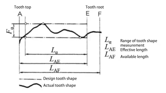
3. Tooth line error

4. Tone error

Measure the pitch value on the measuring circle centered on the gear shaft.
Single tooth pitch deviation (fpt) is the difference between the actual pitch and the theoretical pitch.
Total cumulative pitch deviation (Fp) is used to evaluate the deviation of the entire gear pitch. The total amplitude value of the cumulative tone deviation curve represents the total tone deviation.
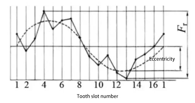
5. Radial eccentricity (Fr)
Place a probe (spherical or cylindrical) successively in the tooth groove and measure the difference between the maximum and minimum radial distances from the probe to the gear shaft. Gear shaft eccentricity is one of the factors contributing to radial runout.
6. Radial Composite Deviation (Fi”)
So far, the methods we have described for evaluating the accuracy of gears, such as tooth shape, pitch, and tooth flank accuracy, are all methods for evaluating the accuracy of an individual gear.
In contrast, there is another method that evaluates gear accuracy by performing a two-tooth meshing test on the gear in combination with a measuring gear. The two surfaces of the tested gear mesh with the measuring gear and rotate for an entire cycle. The change in center distance is recorded.
The figure below shows the test results for a gear with 30 teeth. There are a total of 30 wave lines for the composite radial runout of a single tooth.
The radial compound runout value is approximately the sum of the radial runout runout and the single tooth radial compound runout.

7. The correlation between various aspects of gear accuracy
The various parts of gear precision are related to each other. Generally speaking, radial deviation is strongly correlated with other errors, and there is also a strong correlation between various pitch errors.

8. The requirements for high precision gears are:

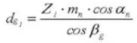
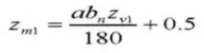
8. Gear calculation formulas:
Spiral angle in a normal cylindrical section:

Spiral angle on a base cylinder:

Tooth thickness centering angle:

Pin diameter:

Center distance correction factor:

Calculation of standard spur gears (pinion ①, sprocket ②)
1. Number of teeth on standard gear
2. Spur gear with standard involute gear profile
3. Module m
4. Pressure angle

5. Number of teeth

6. Effective Tooth Depth

7. The entire depth of the tooth

8. Gear backlash

9. Reference partial circle diameter

10. Outer Diameter

11. Root Diameter

12. Base Circle Diameter
13. Circular step

14. Normal diametrical pitch

15. Circular Tooth Thickness
16. Thickness of the chordal tooth

17. Gear oil dipstick tooth height
18. Number of transverse teeth
19. Tooth thickness
20. Pin diameter

21. Cylindrical measuring dimension

Formula for calculating offset spur gears (pinion ①, gear ②):
1. Gear tooth cross profile
2. Tool tooth profile contact ratio
3. Module m
4. Pressure angle

5. Number of teeth Z
6. Effective Tooth Depth

7. The entire depth of the tooth

8. Gear C backlash
9. Transverse contact relationship
10. Central Distance

11. Reference partial circle diameter

12. Operating pressure angle

13. Pitch circle diameter

14. Outer Diameter

15. Additional diameter
16. Pitch diameter
17. Circular Step

18. Normal diametric step

19. Circular Tooth Thickness

20. Chordal tooth thickness

21. Gear Vernier Caliper Tooth Height

22. Number of transverse teeth

23. Tooth thickness transversely
24. Tip diameter

25. Transverse Measurement Dimension

Formula for calculating standard helical gears (normal system) (pinion ①, gear ②)
1. Gear tooth profile pattern
2. Reference section of the normal tooth profile system
3. Tool tooth profile helical gear
4. Module

5. Pressure Angle
6. Number of teeth

7. Propeller Direction

8. Effective Tooth Depth

9. The entire depth of the tooth

10. Front pressure angle
11. Central Distance

12. Reference partial circle diameter

13. Outer Diameter

14. Root Diameter

15. Pitch diameter
16. Helix Angle at the Base Circle

17. Argument

18. Circular Step (Normal System)

19. Normal Diametral Pitch (Normal System)

20. Circular Tooth Thickness (Normal System)

21. Equivalent number of teeth in a standard spur gear

22. Thickness of the chordal tooth

23. Gear Vernier Caliper Tooth Depth

24. Number of transverse teeth

25. Tooth thickness transversely

26. Tip diameter

27. Cylindrical measuring dimension

28. Gear backlash f
Formula for calculating displaced helical gears (normal system) (pinion ①, gear ②):
1. Shifted gear tooth profile
2. Reference section of the normal tooth profile system
3. Tool tooth profile helical gear
4. Module (Normal System)

5. Pressure Angle (Normal System)

6. Number of teeth

7. Propeller Direction

8. Effective Tooth Depth

9. The entire depth of the tooth

10. Transverse contact relationship

11. Central Distance
12. Normal Module

13. Frontal Pressure Angle (Normal System)

14. Equivalent number of teeth in a standard spur gear

15. System normal pressure angle

16. Reference partial circle diameter

17. Outer Diameter

18. Pitch diameter of teeth in contact

19. Pitch diameter

20. Helix Angle on Base Cylinder

21. Circular Tooth Thickness

22. Thickness of the chordal tooth

23. Gear Vernier caliper tooth height.

24. Number of transverse teeth
25. Tooth thickness transversely

26. Pin diameter.

27. Cylindrical measuring dimension