1. Steel ruler, calipers (internal and external) and micrometer.
(1) Steel ruler
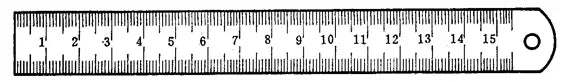
A steel ruler is the simplest length measuring tool available and comes in four sizes: 150mm, 300mm, 500mm and 1000mm. The following image shows a commonly used 150mm steel ruler.
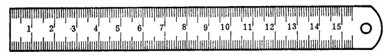
Steel rulers are used to measure the length dimensions of parts, but their measurement results are not very accurate. This is because the spacing between the markings on a steel ruler is 1 mm and the width of each marking is between 0.1-0.2 mm.
Therefore, during measurement, significant reading errors may occur. Only millimeter values can be read and the smallest reading value is 1 mm. Values smaller than 1 mm can only be estimated.
Method of using steel ruler.
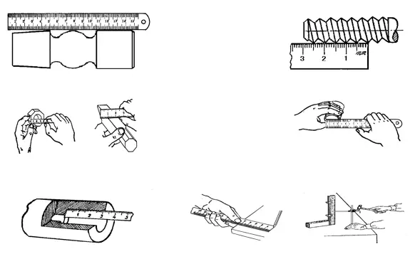
a) Measure the length.
b) Measure the thread pitch.
c) Measure the width.
d) Measure the internal diameter.
e) Measure the depth.
f) Draw lines.
Directly measuring the diameter (shaft or hole) size of a part with a steel ruler will result in lower measurement accuracy. The reason for this is that, in addition to the large error in reading the steel ruler itself, it is difficult to position the steel ruler in the correct position on the diameter of the part.
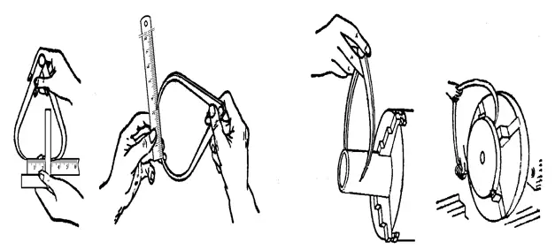
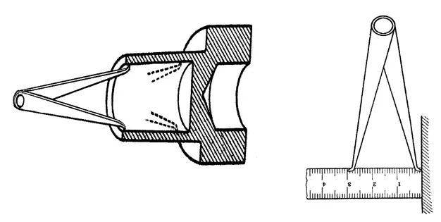
Therefore, to measure the diameter size of parts, a combination of a steel ruler and internal/external calipers can be used.
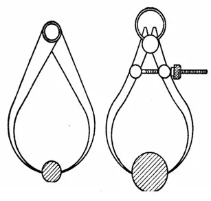
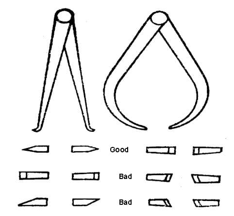
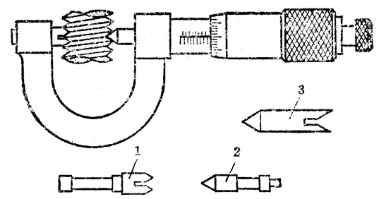
2. Internal/external forceps.
There are two common types of forceps, internal and external forceps. Inside calipers are generally used to measure inside diameters and grooves, while outside calipers are used to measure outside diameters.
They cannot directly read the measurement results, but instead transfer the length measurement to a steel ruler for reading or take the required size from the steel ruler and then check whether the diameter of the part complies.
Calipers are simple measuring tools, characterized by simplicity in structure, ease of manufacture, low cost, maintenance and use.
They are widely used to measure and inspect parts with low dimensional requirements, particularly to measure and inspect forged and cast parts. Calipers are the most suitable measuring tool for these applications.

3. Feel meter.
Feeler gauge, also known as feeler gauge or feeler gauge.
It is mainly used to check the gap size between two mating surfaces.
The feeler gauge is composed of many layers of steel sheets with varying thicknesses. They are grouped into sets and each set contains several gauges. Each feeler gauge part has two parallel measuring surfaces and thickness markings for combined use.
During measurement, one or more feeler gauge parts are superimposed and inserted into the gap according to the size of the gap between corresponding surfaces.
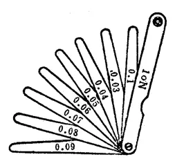
For example, if a 0.03mm gauge can be inserted into the gap while a 0.04mm gauge cannot, this indicates that the gap is between 0.03mm and 0.04mm, making the feeler gauge a limit meter type.
When using a feeler gauge, the following points must be observed:
Select the appropriate number of gauges according to the space between the contact surfaces, but use as few gauges as possible.
Do not apply too much force during measurement to avoid bending or breaking the feeler gauge.
Do not measure workpieces at high temperatures.
2. Vernier scale measuring instrument.
Vernier calipers are measuring tools made using the Vernier scale principle. They include caliper, height gauge with vernier scale, depth gauge with vernier scale, protractor angle gauge (such as universal bevel protractor) and gear tooth caliper.
These tools are used to measure the outer diameter, inner diameter, length, width, thickness, height, depth, angle and gear tooth thickness of parts and have a wide range of applications.
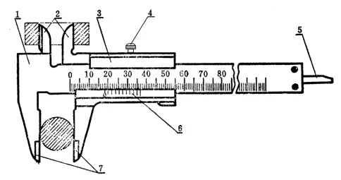
1. Caliper
The caliper is a commonly used measuring tool, characterized by its simple structure, convenient use, moderate accuracy and a wide range of measured sizes.
It can be used to measure the outer diameter, inner diameter, length, width, thickness, depth, hole spacing of parts, etc., and has a wide range of applications.
There are three types of structural shapes for the caliper.
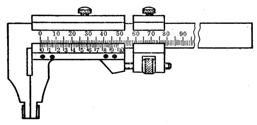
(1) Vernier caliper with a measuring range of 0 to 125 mm, made in the form of a knife-shaped upper and lower jaw and equipped with a depth gauge.
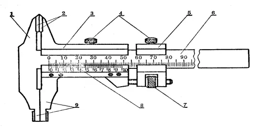
(2) Vernier calipers with measuring ranges of 0-200mm and 0-300mm can be made in the form of lower jaws with internal and external measuring surfaces and upper jaws with a knife-edge shape.
(3) Vernier calipers with measuring ranges of 0-200mm and 0-300mm can also be made in the form of lower jaws with only inner and outer measuring surfaces.
The measuring range and corresponding reading values of the Vernier caliper.
| Measuring range | Cursor read value | Measuring range | Cursor read value |
| 0~25 | 0.02 0.05 0.10 |
300~800 | 0.05 0.10 |
| 0~200 | 0.02 0.05 0.10 |
400~1000 | 0.05 0.10 |
| 0~300 | 0.02 0.05 0.10 |
600~1500 | 0.05 0.10 |
| 0~500 | 0.05 0.10 |
800~2000 | 0.10 |
The reading principle and method of the Vernier caliper.
For a Vernier caliper with a reading value of 0.1 mm, the distance between each line of the main scale is 1 mm.
When the zero line on the Vernier scale is aligned with the zero line on the main scale (the jaws are closed), the 10th line on the Vernier scale points exactly at 9mm on the main scale, while none of the other lines on the Vernier scale line up with any lines on the main scale.
The measuring range of the caliper is calculated as follows:
Range = 9mm ÷ 10 = 0.9mm
The difference between the main scale range and the vernier scale range is:
1mm – 0.9mm = 0.1mm
Therefore, the minimum reading that can be obtained from the caliper is 0.1 mm, and no lower value can be measured.
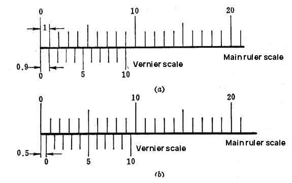
A caliper with a vernier scale reading of 0.05 mm.
When the two jaws are closed and the distance between them is 39 mm as indicated by the main scale, the vernier scale of this caliper is divided into 20 equal parts. Therefore, the distance between each division on the vernier scale is calculated as follows:
Distance between divisions on the vernier scale = 39mm ÷ 20 = 1.95mm
The difference between the distance of two divisions of the main scale (2 mm) and the distance of one division of the vernier scale (1.95 mm) is:
2mm – 1.95mm = 0.05mm
Therefore, the minimum reading value of this caliper is 0.05 mm.
Similarly, if the vernier scale has 20 divisions, but the distance between the jaws is only 19 mm according to the main scale, the same principle applies.
A caliper with a vernier scale reading of 0.02 mm.
When the two jaws are closed and the distance between them is 49 mm as indicated by the main scale, the vernier scale of this caliper is divided into 50 equal parts. Therefore, the distance between each division on the vernier scale is calculated as follows:
Distance between divisions on the vernier scale = 49mm ÷ 50 = 0.98mm
The difference between the distance of one division of the main scale (1 mm) and the distance of one division of the vernier scale (0.98 mm) is:
1mm – 0.98mm = 0.02mm
Therefore, the minimum reading value of this caliper is 0.02 mm.
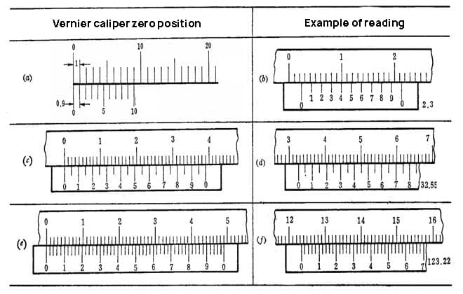
(a) A caliper with a vernier scale reading of 0.1 mm.
(b) A caliper with a vernier scale reading of 0.05 mm.
(c) A caliper with a vernier scale reading of 0.02 mm.
The measurement accuracy of the Vernier caliper.
When measuring or inspecting the size of a part, it is necessary to select an appropriate measuring tool according to the accuracy requirements of the part size. The Vernier caliper is a medium precision measuring tool, suitable only for measuring and inspecting medium precision dimensions.
It is unreasonable to use Vernier caliper to measure raw castings or dimensions with high precision requirements.
The former can easily damage the measuring tool, while the latter cannot achieve the required measuring accuracy, since all measuring tools have certain indication errors, which are listed in the table below.
| Reading value | Total indication error |
| 0.02 | ±0.02 |
| 0.05 | ±0.05 |
| 0.10 | ±0.10 |
The Vernier caliper indication error is due to the manufacturing precision of the caliper itself. No matter how correctly it is used, the calibrator can still produce these errors.
For example, when using a Vernier caliper with a reading value of 0.02 mm and an indication error of ±0.02 mm to measure a shaft with a diameter of 50 mm, if the reading on the caliper is 50.00 mm, the diameter Actual may be 50.02mm or 49.98mm.
When using Vernier calipers to measure part sizes, the following points must be observed:
1. Before measuring, the caliper must be cleaned and inspected to ensure that both measuring surfaces and measuring edges are flat and undamaged. When the two jaws are well adjusted, there should be no obvious gaps, and the zero marking lines of the vernier and main scale should be aligned with each other. This process is called checking the zero position of the caliper.
2. When moving the gripper frame, it should move smoothly without being too loose or tight, and there should be no vibration. When fixing the caliper frame with a set screw, the caliper readings should not change. When moving the caliper structure, don't forget to loosen the fixing screw, and don't loosen it too much to avoid losing control.
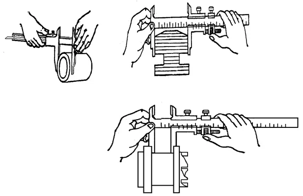
3. When measuring the external dimensions of the measured parts, the connecting line between the two measuring faces of the caliper must be perpendicular to the surface being measured and must not be distorted. During measurement, the caliper can be gently rocked to align it vertically. Never adjust the two caliper jaws to be close to or even smaller than the measured size and force the caliper into the part. This will cause the jaws to deform or the measuring surfaces to wear prematurely, causing the caliper to lose the required accuracy.
Correct measurement method
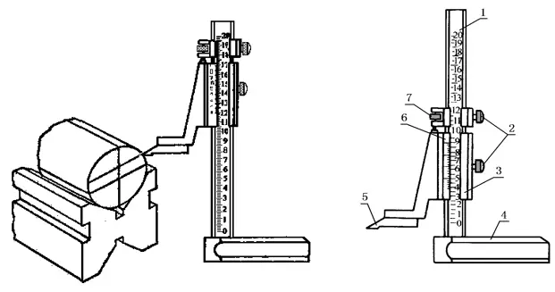
2. Vernier Caliper Height Gauge
The Vernier Caliper Height Gauge, as shown in the image, is used to measure the height of parts and mark accurately.
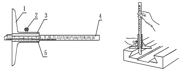
3. Vernier Caliper Depth Gauge
Vernier Caliper Depth Gauge as shown in the picture is used to measure the depth dimension or step height and groove depth of parts.
4. Vernier caliper with tooth thickness
Vernier caliper with tooth thickness is used to measure the thickness of the chordal tooth and the top of the chordal tooth of gears (or helical gears). This type of Vernier caliper consists of two perpendicular main scales, each with its own Vernier scale.
All types of Vernier calipers mentioned above share a common problem: the readings are not very clear and can be easily misinterpreted. Sometimes it is necessary to use a magnifying glass to enlarge the reading portion.
To eliminate the parallax error caused by the tilt of the line of sight during reading, some calipers are equipped with micrometers, becoming micrometer calipers, which facilitate accurate reading and improve measurement accuracy.
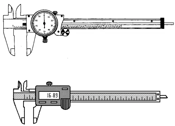
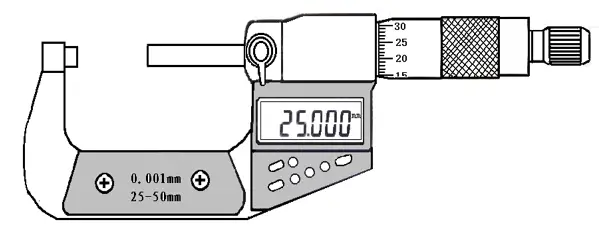
There is also a type of Vernier caliper with a digital display, which directly displays in numbers the dimensions measured on the surface of the part. Its use is extremely convenient.
3. Thread micrometer
Instruments made using the screw micrometer principle are called screw micrometers. They have a higher measurement accuracy than Vernier calipers and are more flexible in measurement, so they are often used when high machining accuracy is required.
Commonly used screw micrometers have scales with graduations of hundredths of a millimeter (0.01 mm) and thousandths of a millimeter (0.001 mm).
Currently, in workshops, a large number of thread micrometers are used with a reading of hundredths of a millimeter (0.01 mm).
There are many types of hundredths of a millimeter reading scales, which are commonly used in mechanical machining shops, including outer diameter micrometers, inner diameter micrometers, depth micrometers, thread micrometers and gear tooth thickness micrometers.
They are respectively used to measure or inspect the outer diameter, inner diameter, depth, thickness, thread midpoint and normal length of the gear.
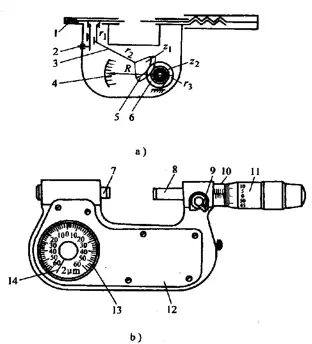
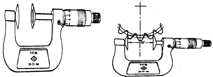
1. Structure of Outer Diameter Micrometer
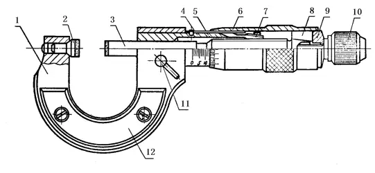
1. Frame; 2. Fixed measuring anvil; 3. Measuring screw; 4. Threaded spindle sleeve; 5. Fixed scale sleeve; 6. Vernier sleeve; 7. Adjustment nut; 8. Connector; 9. Washer; 10. Force measuring device; 11. Locking screw; 12. Insulating plate.
Vernier caliper reading method
The micrometer's circular scale is marked with 50 equally spaced lines, and when the micrometer is turned one full turn, the measuring screw advances or retracts 0.5 mm.
When the micrometer body rotates a small division on its own circular scale, the distance between the two rotating measuring surfaces is:
0.5÷50 = 0.01 (mm).
Therefore, it can be known that the spiral reading mechanism on the caliper can read the value of 0.01mm correctly, which means the reading value of the caliper is 0.01mm.
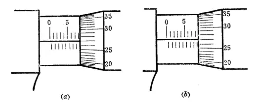
The specific caliper reading method can be divided into three steps:
(1) Read the size of the graduation line exposed on the fixed sleeve and pay attention not to miss the value of the 0.5mm graduation line that should be read.
(2) Read the size on the micrometer body and see which division on the circumference of the micrometer body aligns with the reference center line of the fixed sleeve. Multiply the number of divisions by 0.01 mm to get the size of the micrometer body.
(3) Add the above two numbers to get the size measured on the caliper.
As shown in Figure (a), the size read on the fixed sleeve is 8 mm and the size read on the micrometer body is 27 (divisions) x 0.01 mm = 0.27 mm. Adding the above two numbers gives a measured size of the part being inspected as 8.27 mm.
In Figure (b), the size read on the fixed sleeve is 8.5 mm and the size read on the micrometer body is 27 (divisions) x 0.01 mm = 0.27 mm. Adding the above two numbers gives a measured size of the part being inspected as 8.77 mm.
When using a caliper to measure the dimensions of a part, pay attention to the following points:
(1) Before use, clean the two measuring faces of the caliper and rotate the measuring force device to make contact with the two measuring faces (if the upper measuring limit is greater than 25mm, insert an adjustment gauge or block of corresponding size between the two measuring faces), and there should be no gap or light leakage phenomenon on the contact surface. At the same time, briefly align the micrometer and fixed sleeve with zero.
(2) When rotating the force measuring device, the micrometer must be able to move freely along the fixed sleeve without any binding or inflexibility.
(3) Before measurement, clean the measured surface of the part to avoid affecting the measurement accuracy due to the presence of dirt. It is absolutely not permitted to use a caliper to measure abrasive surfaces in order to avoid damaging the accuracy of the measuring surface. Measuring parts with rough surfaces using a caliper is also incorrect as it can cause premature wear of the measuring faces.
(4) When using a caliper to measure a part, hold the rotating cover of the force measuring device to rotate the micrometer screw, so that the measuring face maintains the standard measuring pressure, that is, when you hear a “click” sound, indicating that the pressure is appropriate, and you can start reading the measurement. Be sure to avoid measurement errors caused by uneven measuring pressure.
(5) When using a caliper to measure parts, make sure the micrometer screw is aligned with the direction of the part being measured.
(6) When measuring a part with a caliper, it is best to read the measurement while it is still on the part and then remove the caliper after releasing the pressure. This can reduce wear on the measuring faces.
(7) When reading the measurement value on the caliper, pay special attention not to misinterpret 0.5 mm.
(8) To obtain accurate measurement results, it is recommended to take a second measurement at the same position.
(9) For workpieces that are abnormally hot, do not take measurements to avoid reading errors.
(10) When using an external caliper with one hand, hold the movable glove with your thumb and index or middle finger, hook your little finger into the frame, and press it against your palm. Then rotate the force measuring device with your thumb and index finger to take the measurement.
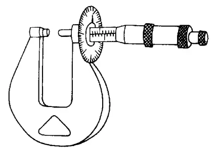
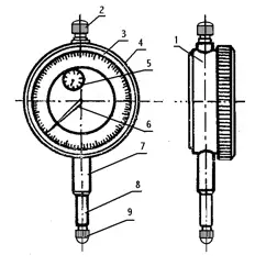
Lever Dial Indicator
The lever comparator, also known as the comparison test indicator, is a precision measuring instrument composed of the micrometric part of an outside micrometer and the indicating mechanism of a lever-type depth gauge.
A dial indicator, also known as a dial indicator, is the main tool used to find the center of a shaft or other cylindrical part. It measures small linear distances and provides accurate readings to ensure alignment and accuracy during machining processes.
Inside the Vernier caliper
The inner caliper, as shown in the image, is read using the same method as the outer caliper.
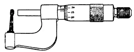
Depth Vernier Caliper
Depth caliper, as shown in the picture, is used to measure small internal diameters and groove widths on internal surfaces. Its feature is that it is easy to find the correct diameter of an internal hole and is convenient to use for measurements.
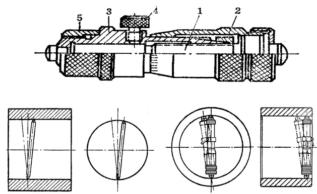
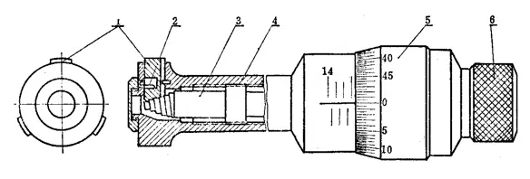
Three Jaw Inside Micrometer
The three-jaw inside micrometer is suitable for measuring the precise inner diameter of small and medium holes, especially for measuring the diameter of deep holes.
Measuring range (mm) includes: 6-8, 8-10, 10-12, 11-14, 14-17, 17-20, 20-25, 25-30, 30-35, 35-40, 40 - 50, 50-60, 60-70, 70-80, 80-90, 90-100.
The zero position of the three-jaw inside micrometer must be calibrated within a standard hole.
Gear tooth vernier caliper
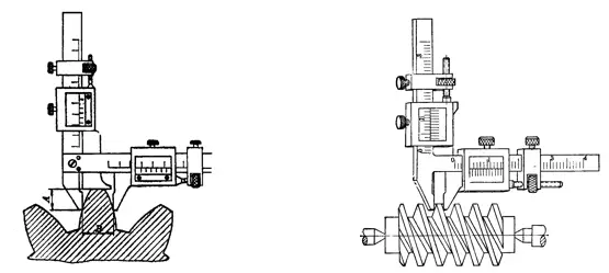
The gear tooth caliper as shown in the picture is mainly used to measure the lengths of two different normal lines on the externally meshed cylindrical gears.
It can also be used to check the original dimensions of a gear shape along its normal line when inspecting the accuracy of a gear cutting machine.
Its structure is similar to the external caliper, except that it has two measuring jaws (measuring faces) with precise planes installed on the measuring surface instead of the original measuring faces.
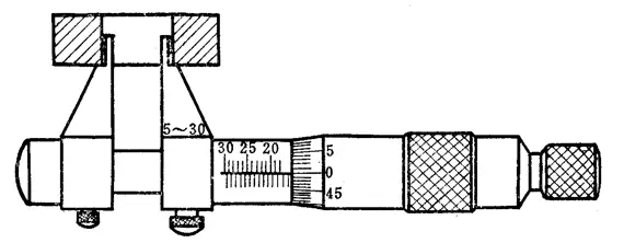
Wall Thickness Vernier Caliper
The wall thickness caliper as shown in the picture is mainly used to measure the wall thickness of precision tubular parts. The measuring faces of the wall thickness caliper are inlaid with hard alloy to improve its service life.
Measuring range (mm): 0-10, 0-15, 0-25, 25-50, 50-75, 75-100. Reading value (mm) 0.01
Vernier Thickness Caliper
Thickness caliper as shown in the picture is mainly used to measure the thickness dimension of sheet metal.
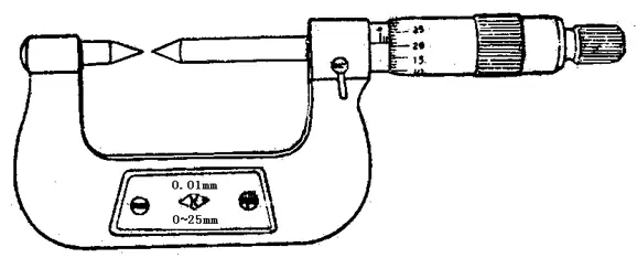
Vernier caliper with pointed jaw
Pointed jaw caliper as shown in the picture is mainly used to measure the thickness, length, diameter and small grooves of parts. For example, it can be used to measure the groove diameter of even threaded drills and taps.
Thread Vernier Caliper
The thread caliper, as shown in the picture, is mainly used to measure the pitch diameter of a standard thread.
1, 2 Two-point measuring head 3. Setting ring
Depth Vernier Caliper
Depth caliper as shown in the picture is used to measure hole depth, groove depth, step height and other dimensions. Its structure is similar to that of an external caliper, except that it has a base instead of a frame and measuring face.
- Force Measuring Device
- Dial meter
- Fixed sleeve
- Locking device
- Base plate
- Measuring rod.
Vernier External Digital Caliper
Recently, external digital calipers are becoming more popular in China due to their ease of use. These calipers display readings digitally, which eliminates the need for manual interpretation.
Some digital calipers also have a fixed sleeve with markings that allow readings as small as 0.002 mm or up to 0.001 mm using a graduated cursor.
4. Gauge block
The use and accuracy of gauge blocks
The gage block, also known as the “gauge block”, is the most fundamental measuring tool used in the machine manufacturing industry. It serves as an intermediary in transferring measurements between a standard length and the dimensions of a part.
Gauge blocks are a reference for length measurement in technical measurements due to their high precision.
The working size of a gauge block does not refer to the distance between any two measuring surfaces because these surfaces are not absolutely parallel.
Therefore, the working size of a gauge block refers to its center length, which is the vertical distance from the center of one measuring surface to the gluing surface (whose surface quality is consistent with that of the gauge block) of the other measuring surface.
Each gauge block is marked with its working size: when the gauge block size is equal to or greater than 6 mm, the working mark is on a non-useful surface; when the gauge block is less than 6mm, the working size is marked directly on the measuring surface.
Gauge blocks are classified into five grades of accuracy based on the accuracy of their working sizes (i.e., center lengths) and the accuracy of the flatness parallelism between the two measuring surfaces.
These grades are 00, 0, 1, 2 and 3. The accuracy of grade 0 gage block is the highest, with very accurate work sizes and flatness parallelism, and an error of just a few microns. They are generally used by provincial and municipal metrology institutes to calibrate precision instruments.
The accuracy of the 1-degree standard block is slightly lower, followed by the 2-degree standard block. The gauge block accuracy of 3 degrees is the lowest and is generally used in factory or workshop measuring stations to calibrate commonly used precision measuring tools.
Gauge blocks are dimensional patterns that are precise and difficult to manufacture.
To ensure that gauge blocks with larger deviations in working sizes can still be used as accurate length standards, their working sizes can be checked more accurately and the gauge block calibration correction value is added during use.
Although this method can be more complicated to use, it allows gauge blocks with larger deviations to still be used as accurate dimensional standards.
Gauge blocks are accurate measuring tools and the following points should be noted when using them:
Before use, wash the anti-rust oil with gasoline and then wipe it with a clean chamois or soft cloth. Do not use cotton thread to clean the working surface of the gauge block to avoid damaging the measuring surface.
Do not directly handle the clean gauge block with your hands; instead, place it on a soft cloth before handling it. If you must handle the pattern block with your hands, wash your hands first and hold the block on the non-working surface.
When placing the gauge block on a workbench, the non-functional surface of the block must contact the work surface. Do not place gauge block on plants because residual chemicals on the surface of the plant may cause rust on the gauge block.
Do not push or rub the working surface of the gauge block against the non-working surface to avoid scratching the measuring surface.
After use, immediately clean the indicator block with gasoline, dry it with a soft cloth, apply anti-rust oil and store it in a dedicated box. If frequent use is required, the gauge block can be stored in a drying cylinder after cleaning without applying anti-rust oil.
It is absolutely not allowed to keep gauge blocks glued together for a long time to avoid unnecessary damage caused by metal bonding.
5. Indicating measuring tools
Indicator measuring tools are measuring instruments that indicate measurement results via a pointer.
Indication measuring tools commonly used in workshops include dial gauges, digital gauges, lever gauge gauges, and bore gauges.
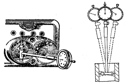
They are mainly used to calibrate the installation position of parts, check the shape accuracy and mutual position accuracy of parts, as well as measure the inner diameter of parts, etc.
Dial indicators and digital indicators are used to calibrate the installation positions of parts or accessories, as well as checking the shape accuracy or mutual position accuracy of parts.
There is not much difference in structural principle between them, except that the reading accuracy of digital indicators is higher. The reading value of a digital indicator is 0.001 mm, while that of a dial indicator is 0.01 mm.
Digital dial indicators and indicators are divided into three degrees of precision, 0, 1 and 2, with degree 0 having greater precision. When using dial indicators or digital indicators, you must choose the appropriate degree of accuracy and measuring range according to the shape and accuracy requirements of the part.
When using dial indicators or digital indicators, pay attention to the following:
(1) Before use, check the flexibility of the measuring rod. Gently push the measuring rod and it should move flexibly within the sleeve without any binding. After each relaxation, the pointer must return to its original position.
(2) When using a dial indicator or digital indicator, it must be fixed to a reliable fixing device (such as a universal table stand or magnetic base). The clamping device must be placed stably to avoid inaccurate measurement results or damage to the dial indicator due to instability.
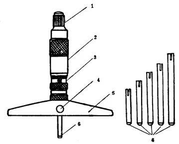
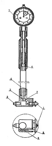
Inner diameter indicator:
An internal diameter indicator is a combination of an internal measuring lever-type structure and a dial indicator, as shown in the figure. It is used to measure or check the inner hole, deep hole diameter and shape accuracy of parts.
6. Angle measuring tools
Universal Angle Ruler:
A universal angle ruler is an angle measuring tool used to measure the internal and external angles of precision parts or to draw angled lines. Includes a protractor and a universal angle ruler.
The scale lines on the base of the universal angle ruler are marked every 1º. Since there are 30 grids on the cursor, the total angle covered by them is 29º.
Therefore, the difference in degree between each gridline is:
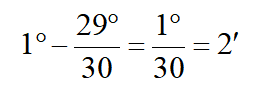
Yes, the accuracy of the universal angle ruler is 2′.
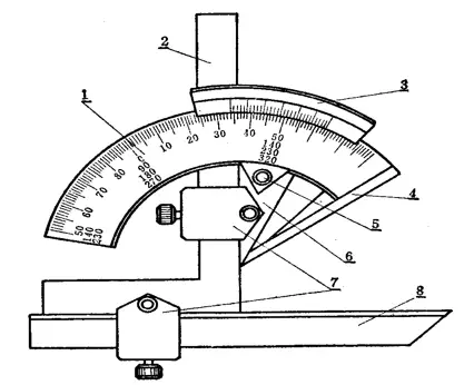
The reading method of the universal angle ruler is similar to that of a caliper. First, read the value of the angle before the zero line of the cursor, and then read the value of “minutes” on the cursor scale. The sum of these two values is the measured angle value of the workpiece.
In the universal angle ruler, the base ruler 4 is fixed to the base, and the angle ruler 2 is fixed to the circular plate with a locking block 7. The movable ruler 8 is fixed to the angle ruler by a locking block.
If the angle ruler 2 is removed, the straight ruler 8 can be fixed to the circular plate. Because the angle ruler 2 and straight ruler 8 can be moved and exchanged, the universal angle ruler can measure any angle from 0° to 320°, as shown in the following figure.
As shown in the figure above, when the angle ruler and straight ruler are fully assembled, the universal angle ruler can measure exterior angles from 0° to 50°.
When only the straight ruler is installed, it can measure angles from 50° to 140°. When only the angle ruler is installed, it can measure angles from 140° to 230°.
When the angle ruler and straight ruler are removed, it can measure angles from 230° to 320° (that is, interior angles from 40° to 130°).
On the scale lines on the base of the universal angle ruler, the basic angle markings are only from 0° to 90°. If the angle being measured is greater than 90°, a base value (90°, 180°, 270°) must be added to the reading. When the measured angle range is:
- 90° to 180°, the measured angle = 90° + reading from the angle measuring tool
- 180° to 270°, the measured angle = 180° + reading from the angle measuring tool
- 270° to 320°, the measured angle = 270° + reading from the angle measuring tool
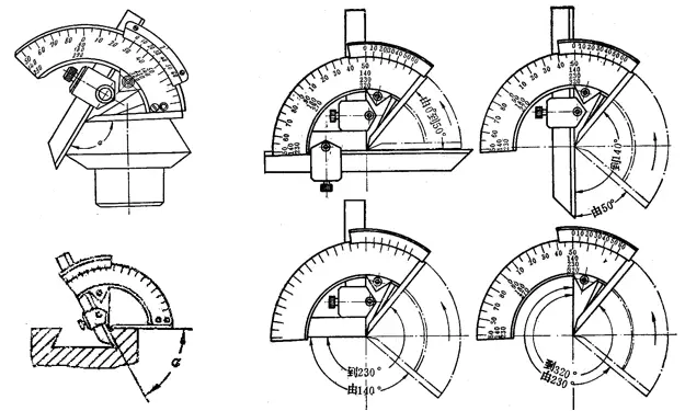
Universal bevel protractor
The universal bevel protractor is shown in the figure. It is mainly used to measure general angles, lengths, depths, horizontality, as well as locating the center on circular parts.
It is also known as Universal Steel Angle Ruler, Universal Angle Protractor and Combination Angle Ruler. It consists of a steel ruler (1), a movable protractor (2), a central angle gauge (3) and a fixed angle gauge (4). The length of its steel ruler is 300 mm.
1- Steel ruler
2- Mobile protractor
3- Central angle meter
4- Fixed angle meter
Protractor with Vernier scale
The Protractor with Vernier Scale is shown in the figure. It is used to measure any angle and has a higher measurement accuracy than a general protractor. The measuring range is 4×90º, with a reading value of 2′ and 5′, and a range of 0-360º with a graduation value of 5′.
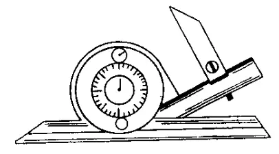
Central Meter
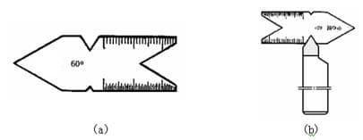
The central meter is shown in figure (a). It is mainly used to inspect the angle of threads and threading tools (shown in figure (b)) and to correct the position of threading tools during installation.
When cutting threads, higher requirements are placed on the installation of threading tools in order to ensure the correct tooth shape. For triangular threads, the shape of the teeth must be symmetrical and perpendicular to the axis of the part, that is, the two half-angles are equal.
To equalize the two half-angles during installation, the center gauge can be used as shown in figure 6-9. The accuracy of the lathe's upper needle can also be checked. It comes in two specifications: 55º and 60º.
Sine bar
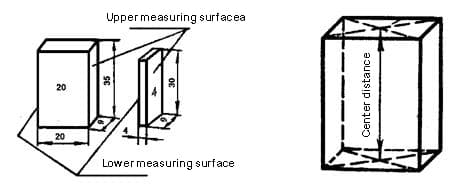
The sine bar is a measuring tool used to accurately check the angles and tapers of parts and gauges. It is measured using the sine trigonometric ratio, hence its name as sine bar or sine rule.
The main body of the sine bar has precision working surfaces and two precision cylinders, and can be equipped with four stops (of which only two are installed when in use) perpendicular to each other as positioning plates for placing parts during measurement .
There are two types of household sine bars: wide and narrow.
Sine bar specifications.
| Center distance between two cylinders | Cylinder diameter | Countertop width (mm) | Accuracy level |
| (mm) | (mm) | wide strait | |
| 100 | 20 | 25 80 | level 0.1 |
| 200 | 30 | 40 80 |
The following figure is a schematic diagram of measuring the taper angle of a taper gauge using a sine bar.
When using a sine bar to measure the angle of a part, such as a taper gauge, first place the sine bar on a precision platform and place the part to be measured on the working surface of the sine bar, with the positioning surface of the part to be measured resting against the stop of the sine bar (such as the front face of the taper meter against the front stop of the sine bar).
Place a gauge block under one of the sine bar cylinders and use a dial gauge to check the height of the part along its entire length.
Adjust the gauge block size so that the dial indicator reading is the same across the entire length of the part. At this point, you can use the formula for the sine of a right triangle to calculate the angle of the piece.
Sine formula:
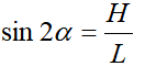
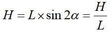
Where:
- sin is the symbol of the sine function,
- 2α is the conicity angle (in degrees) of the cone,
- H is the height (mm) of the gauge block,
- L is the central distance (mm) between the two cylinders of the sine bar.
For example, when measuring the taper angle of a taper gauge using a narrow sinusoidal bar with a center distance L = 200 mm, and when the gauge block is placed under a cylinder with a height H = 10.06 mm, the gauge with dial reads the same along the entire length of the tapered plug gauge. At this time, the calculation of the taper angle of the taper gauge is as follows:
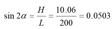
Consulting the sine function table, we obtain 2α=2º53′. Therefore, the actual taper angle of the taper gauge is 2º53′.
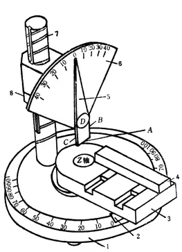
Tool Angle Measuring Holder
The tool angle measuring holder is a special instrument used to measure the angles of cutting tools. It consists of a base 1, an indicator board 2, a platform 3, a positioning block 4, a pointer 5, a sector plate 6, a column 7 and a nut 8. The base 1 is disc-shaped with scales of 100 ° on both sides of the zero line. The platform 3 can rotate left and right around the Z axis on the base, and the rotation angle can be indicated by the indicator plate 2 fixed at the bottom of the platform. The sector 6 plate has scales of ±45°. Pointer 5 can rotate around its axis, and the angle of rotation can be indicated on the scale of the sector plate. The lower end of the pointer 5 is a measuring plate, which has a lower blade A, a right blade B, a left blade C and a front measuring surface D. The column 7 has threads. Turning nut 8 can move sector plate 6 up and down.
7. Spiritual level
The spirit level is a measuring tool commonly used to measure changes in angle. It is mainly used to measure the horizontal position of machine parts relative to each other and the flatness, straightness and perpendicularity of equipment during installation. It can also measure the small inclination of the parts.
Commonly used spirit levels include line spirit levels, frame spirit levels and digital optical collimator spirit levels, etc.
Line spirit level
The following figure shows a common line spirit level used by mechanics. The line spirit level consists of a V-shaped base surface as the working surface and a level (commonly known as the bubble) parallel to the working surface. Both the leveling of the work surface and the parallelism of the level with the work surface are very precise.
When the base surface of the spirit level is placed in a precise horizontal position, the bubble in the level is in the middle position (that is, in the horizontal position).
When there is a small difference between the base surface of the spirit level and the horizontal position (that is, when the two ends of the base surface of the spirit level are at different heights), the bubble in the level always moves in towards the highest side of the level due to the effect of gravity, which is the principle of using the spirit level.
When the height difference between the two ends is small, the bubble also moves only slightly, but when the height difference between the two ends is large, the movement of the bubble is also large, and the height difference between the two ends can be read on the level scale.

Level Meter Specification:
| Varieties | Overall dimensions (mm) | Graduation fee | |||
| far away | wide | high | group | (mm/m) | |
| Box type | 100 | 25~35 | 100 | I | 0.02 |
| 150 | 30~40 | 150 | |||
| 200 | 35~40 | 200 | |||
| 250 | 40~50 | 250 | II | 0.03~0.05 | |
| 300 | 300 | ||||
| Bar shape | 100 | 30~35 | 35~40 | ||
| 150 | 35~40 | 35~45 | |||
| 200 | 40~45 | 40~50 | Ⅲ | 0.06~0.15 | |
| 250 | |||||
| 300 | |||||
Bar Level Gauge Graduation Value Explanation
For example, if the graduation value is 0.03 mm/m, it means that when the bubble moves one grid, the height difference between the two ends of a measured length of 1 m is 0.03 mm. In addition, use a 200 mm long level gauge with a graduation value of 0.05 mm/m to measure the flatness of a 400 mm long plane.
First, place the level gauge on the left side of the plane. If the bubble moves two grids to the right, place the level gauge on the right side of the plane. If the bubble moves three grids to the left, this indicates that the plane is a convex surface that is highest in the middle and lowest on both sides.
How much higher in the middle? Looking from the left side, the middle is two grids higher than the left end, which means that in a measured length of 1m, the middle is 2×0.05=0.10mm taller. Since the actual measured length is 200 mm, which is 1/5 of 1 m, the actual height difference is 0.10 × 1/5 = 0.02 mm higher in the middle than at the left end.
Looking from the right side, the middle is three grids higher than the right end, which means that in a measured length of 1m, the middle is 3×0.05=0.15mm taller. Since the actual measured length is also 200 mm, which is 1/5 of 1 m, the actual height difference is 0.15 × 1/5 = 0.03 mm higher in the middle than at the right end. Therefore, it can be concluded that the height difference between the middle and both ends is (0.02+0.03)÷2=0.025mm.
Box Level Gauge
The following picture shows a commonly used box level gauge, which is mainly composed of a frame 1 and the main circular glass tube level gauge 2 and the adjustment level gauge 3. The movement of the bubble in the level is used to measure the change in angle of the part being measured.
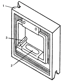
1 – Frame
2 – Main Level Meter
3 – Adjustment level meter
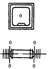
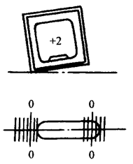
There are two methods of reading the level gauge: direct reading and average reading.
(1) Direct reading method
The long mark lines at both ends of the bubble on the level gauge are used as the zero line, and the number of displacements of the bubble grid relative to the zero line is used as the reading. This method is the most commonly used method, as shown in the figure below.
(2) Average reading method
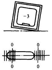
Due to large changes in ambient temperature, the bubble may stretch or contract, causing reading errors and affecting measurement accuracy. To eliminate reading errors, the average reading method can be used.
In the average reading method, readings are taken from both long marking lines towards the end of the bubble in the direction of movement. Then, the average value of these two readings is considered the reading for this measurement.
Due to the high ambient temperature, the bubble became elongated, causing it to shift to the left during the measurement. When reading, start on the long line on the left and read “-3” on the left. Then start at the long mark line on the right and read “-2” on the left. The average of these two readings is considered the reading value for this measurement.