1. Preface
The camshaft is a crucial component in the valve train of an internal combustion engine. It is responsible for regulating the opening and closing of valves according to a specific working sequence and valve phase, ensuring that the valves have adequate lift. As a result, it plays a decisive role in the overall performance of the valve train.
In a four-stroke engine, the rotational speed of the camshaft is half that of the crankshaft. Consequently, the camshaft rotates at a very high speed and must withstand significant torque.
During operation, the cam surface and rocker arm or tappet experience periodic high contact stress and fast relative sliding speed. As a result, the camshaft must possess sufficient toughness and rigidity, while the cam surface must have good wear and impact resistance.
2. Context of the investigation
The Model M product is a large-scale diesel engine designed for marine use. The camshaft of this product is made of Cf53 steel.
During the initial tensile performance test of the camshaft body, the yield strength was low. However, after the supplier made adjustments to the heat treatment process, the yield strength met the required standards, while the tensile strength remained low (as shown in Table 1).
Table 1 Cf53 steel camshaft mechanical properties test
| Project | R i /MPa | R p0.2 /MPa |
| Standard value | 710~850 | ≥400 |
| First test | 717 | 358 |
| Second test | 685 | 408 |
Furthermore, during daily production, the camshaft made of Cf53 steel (equivalent to 55 steel) has the problem of low hardness, measuring below 200 HBW.
To resolve the above-mentioned quality issues, we conducted an investigation and analysis of the production site belonging to the supplier company responsible for manufacturing the M-type camshaft in the early stages. We present improvement measures, which involve adjusting process parameters, including equipment normalization, temperature normalization and cooling speed.
See Table 2 for the process tuning scheme.
Table 2 Adjustment scheme for Cf53 steel camshaft heat treatment process
| Project | Heat treatment facilities | Process route | Cooling method |
| Before adjustment | Cart oven | 820 ℃ normalization | Forced air cooling |
| After adjustment | Pressure Plate Normalization Wire | 840 ℃ normalization | Cold strong wind |
This post analyzes the physical and chemical properties of the improved Cf53 steel camshaft body material and studies the effect of the normalization process on the mechanical properties of the Cf53 steel camshaft. The aim is to provide a reasonable process plan to improve the comprehensive properties of the camshaft.
3. Material analysis
3.1 Chemical composition
The chemical composition of the camshaft was inspected and the results are shown in Table 3, which meet the material specification requirements: Steel Camshaft (Enterprise Standard) Q/WCG 610.22.
Table 3 Chemical composition of cf53 steel camshaft (mass fraction) (%)
| Project | W | Yes | Mn | Cr | No | P | s |
| Standard value | 0.52~0.57 | 0.15~0.35 | 0.60~0.80 | ≤0.35 | ≤0.30 | ≤0.025 | ≤0.035 |
| Detection value | 0.561 | 0.241 | 0.749 | 0.212 | 0.011 | 0.009 | 0.010 |
3.2 Mechanical properties
Tensile properties at room temperature were tested on the tensile testing machine in the physical and chemical laboratory (see Fig. 1).

Fig. 1 Tensile property test
And it detects the hardness of the camshaft test bar.
See Table 4 for camshaft test rod mechanical property test results.
Table 4 results of testing the mechanical properties of the camshaft body
| Project | Heat treatment | R i /MPa | R p0.2 /MPa | A(%) | Z(%) | HardnessHBW |
| Standard value | normalizing | 710~850 | ≥400 | ≥16 | ≥40 | 214~252 |
| 1 # sample | normalizing | 791 | 429 | 18 | 42 | 222 |
| 2 # sample | normalizing | 753 | 409 | 19 | 47 | 226 |
Inspection rates meet the requirements of Steel Camshaft Material Specification (Enterprise Standard) Q/WCG 610.22.
Table 1 compares the mechanical property test results of the Cf53 steel camshaft before and after process adjustment. Mechanical properties, especially tensile strength (RM), show significant improvement after process adjustment.
3.3 Metallographic structure of the body
Figure 2a shows the structure of the camshaft center of model M after corrosion with 4% nitric acid alcohol. A distinct, elongated area with a diameter of 1.5 mm can be observed in position B, which has completely different colors than the surrounding areas. The metallographic structure of this area is shown in Figure 2b.
The structural characteristics of area B are markedly different from those of area A, indicating the formation of regional segregation.
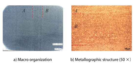
Fig. 2 macrostructure and metallographic structure of the cam shaft after corrosion
Figure 3 shows the metallographic structure of area A in the center of the camshaft for model M.
The metallographic microstructure is evaluated using the metallographic structure classification diagram and evaluation method for forged steel molds in accordance with GB/T 13320-2007.
The core structure consists of pearlite and ferrite, with uniform grain size.
The classification of the structure is grade 2.
According to the GB/T 6394-2002 method for determining the average grain size of metals, the actual grain size of austenite is grade 8, which meets the technical requirements.
Figure 4 shows the metallographic structure of area B in the center of the camshaft for model M.
The core structure is mainly pearlite with a small amount of ferrite distributed, and the pearlite grain is relatively uniform.
Fig. 3 metallographic structure of area 4 of the center of the camshaft
Fig. 4 metallographic structure of area B of the center of the camshaft
The central region of the camshaft bar is the final position for crystallization and contains large amounts of C, S, P and other elements. The WC content of Cf53 steel ranges from 0.52% to 0.57%, and the segregation area of the central component is close to the eutectoid point component. Thus, the pearlite structure mainly forms and only a small amount of ferrite structure is formed.
According to the structural steel macrostructure defect classification diagram GB/T 1979-2001, central segregation is classified as grade 1, which is within the allowable range of technical requirements.
Therefore, it is crucial to control the camshaft center segregation area, improve the purity of the molten steel, adopt a reasonable casting process, and use a large forging rate during the forging and rolling of the blank bar.
Because severe segregation can significantly impact steel quality, segregation defect inspections must be reasonably controlled during sprue bar material inspection to ensure billet quality.
3.4 Metallographic structure of the induction surface hardening layer
See Table 5 for surface induction hardening layer depth and hardness test results of the cam peach tip, base circle, and support journal (see Fig. 5).

Table 5 Camshaft induction paint fire layer detection results
| Peach tip | Base circle | Rolling diary | ||||
| Tempered case/mm | HardnessHRC | Tempered case/mm | HardnessHRC | Tempered case/mm | HardnessHRC | |
| Criterion | 1.5~5.5 | 59~63 | 1.5~3.5 | ≥55 | 1.5~3.5 | ≥55 |
| Test | 5.0 | 61.2 | 3.5 | 63.4 | 3.5 | 63.2 |
Meet standard requirements.
The metallographic structure of the induction hardening layer is shown in Figure 6.
The evaluation of this structure is carried out in accordance with QC/T 502-1999, which is the standard for metallographic inspection of induction hardened automotive parts.
The observed structure is identified as fine needle martensite, classified as grade 4, and meets the requirements of standard 20200718.
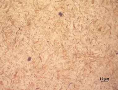
Fig. 6 metallographic structure of the induction hardening layer
3.5 Conclusion
After analyzing the M-type camshaft made of Cf53 steel after process adjustment, the following conclusions can be drawn:
- The chemical composition of the M model camshaft meets the required standards.
- By increasing the normalizing cooling speed, the mechanical properties (tensile strength, yield strength, elongation, area reduction and hardness) of the camshaft can be improved.
- The metallographic structure of the camshaft body of the M model also meets the necessary standards. There is a level 1 central segregation area in the center of the camshaft body with a diameter of 1.5 mm, distributed along the camshaft centerline.
- The metallographic structure of the induction hardening layer of the M-type camshaft is also within the required specifications.
4. Suggestions for improvement
- The supplier is obliged to adhere to the standardization process of the Cf53 steel M-type camshaft in accordance with the guidelines provided during the tuning and trial production phases. In addition, they must improve relevant process documentation.
- Inspection of segregation defects must be managed properly to ensure billet quality during receipt of bar material at the factory.