
The laser cutting process involves absorbing light energy and converting it into thermal energy, which causes the material to melt and vaporize.
The high energy density laser beam is emitted by the laser generator. The beam is then focused through the focusing lens, resulting in a highly concentrated energy source. The focused beam passes through the center of the nozzle, which ejects an auxiliary cutting gas along the same axis as the light path. The combination of the laser beam and cutting gas quickly heats, oxidizes and evaporates the cutting material to achieve the desired cutting effect.
The basic principle behind laser cutting is the interaction between the laser and the matter. This interaction encompasses complex microscopic quantum processes and macroscopic phenomena, such as absorption, reflection, refraction, energy conversion and material transmission to the laser, as well as the state of the material and the composition of the ambient gas.
These macroscopic phenomena, together with other factors such as the tissue effect of a light beam on the surface of a material, make the factors affecting the quality of laser cutting very complex.
In addition to the material being processed, other factors that influence the quality of laser cutting include the characteristics of the light beam, laser power, cutting speed, nozzle type (aperture) and height, focus position, and type and pressure of the laser. auxiliary gas.
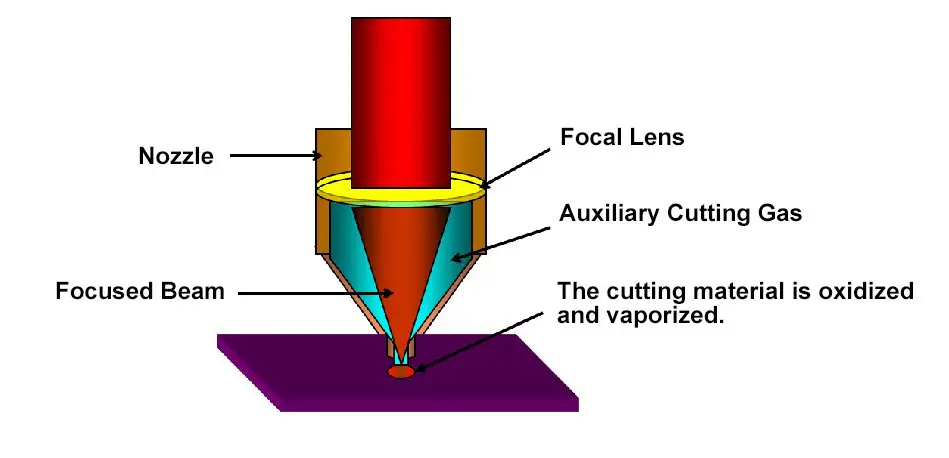
Fig.10 The influence of different focus positions on cutting quality
In actual production, when cutting stainless steel sheets with a laser cutter, the focus position is selected on or within the surface of the material. This is done to increase the fluidity of the cutting gas and melt and improve the cutting quality by increasing the smooth surface area. The position of the focus will vary depending on the thickness of the steel plate and should be determined through experimentation.
The choice of auxiliary gas (type and pressure) also plays an important role in determining the quality of the cut. Gas type, air pressure, nozzle diameter and geometric structure can affect edge roughness and burr formation. Gas consumption is determined by the nozzle diameter and air pressure, with low pressure being less than 0.5 MPa and high pressure being more than 2 MPa. Coaxial ejection of the auxiliary gas and laser beam helps protect the focusing lens from contamination and removes any slag from the cutting area. Gases commonly used for laser cutting include oxygen, nitrogen and air, with different cutting materials requiring different auxiliary gases.
The use of oxygen as an auxiliary gas is mainly for cutting carbon steel, stainless steel and highly reflective materials through high-speed threading and cutting, as well as oxidation cutting. The laser cutting machine uses the heat generated by the oxidation reaction for efficient cutting, but it also results in the formation of an oxide film on the cutting surface.
Nitrogen is mainly used in cutting oxidation-free stainless steel sheets and slag-free galvanized sheets.
Air is mainly used to cut aluminum and galvanized steel without slag and to cut common non-metals.
The auxiliary gas pressure depends on the type of gas used, the cutting material, the thickness of the sheet and the form of laser output (continuous/pulsed wave). Auxiliary gas pressure affects slag holding, cutting surface quality, and the size of the heat-affected area.
The air pressure condition at the nozzle outlet during processing is shown in the following table:
Table 2 The relationship between the cutting process and the auxiliary gas pressure
| Playing | O2 Sheet Metal Cutting | O2 cutting on thick carbon plate | N2 Stainless Steel Cutting | Aluminum Air Cutting | Acrylic Resin Net Surface Cutting |
|---|---|---|---|---|---|
| (MPa) | (MPa) | (MPa) | (MPa) | (MPa) | (MPa) |
| 0.02-0.05 | 0.1-0.3 | 0.05-0.1 | 0.6-1.5 | 0.6-1.0 | <0.01 |
Under the premise of determining the type of auxiliary gas, the size of the gas pressure is an extremely important factor.
If the auxiliary gas pressure is too high, a vortex will form on the surface of the workpiece, which will weaken the ability of the air flow to remove molten material, causing the cutting surface to become rougher and the gap expand.
If the auxiliary gas pressure is too low, the molten material from the incision will not be expelled, leading to the formation of slag on the back of the cut material.
Therefore, there is an ideal value for the auxiliary gas pressure. High gas pressure is required when cutting thin materials at high speed to prevent slag from forming at the back of the incision. On the other hand, when the material thickness increases or the cutting speed decreases, the gas pressure must be reduced appropriately.
For example, when laser cutting stainless steel plates, the use of auxiliary gas helps cool the surrounding areas of the cutting seam, reducing the heat-affected zone and preventing heat damage to the lens.
Furthermore, the use of nitrogen as an auxiliary gas increases the fluidity of the molten metal.
See too:
- The application of air as an auxiliary gas in laser cutting
In actual machining, machining defects may be caused by inappropriate process parameters.
With decades of experience in the laser cutting process, it is important to summarize the countermeasures for cutting defects to guide actual production. See the appendix for more information.
See too:
- 9 Factors That Affect Laser Cutting Quality
Appendix 1 – Laser cutting defects in different materials and troubleshooting
Carbon steel: cutting with O 2
| Defects | Possible reasons | Solution |
|---|---|---|
The traction line at the bottom has a large offset. The burr at the bottom is similar to slag 
|
Very fast feeding speed Low laser power Low laser power High focus position | Reduce feed speed Increase laser power Increase pressure Reduce focal position |
The burr at the bottom is similar to slag, which is drip-shaped and easy to remove. 
|
Very fast feeding speed | Reduce the feeding speed. |
| Low air pressure | Increase the pressure | |
| High focus position. | Lower the focal position | |
The metal burr can be removed as a block. 
|
Very high focal position | Lower the focal position |
The metal burrs on the bottom are difficult to remove. 
|
Very fast feeding speed | Reduce the feeding speed. |
| Low air pressure | Increase the pressure | |
| The gas is not pure | Use purer gas | |
| Very high focal position | Lower the focal position | |
There is only a burr on one side. 
|
The nozzle is not centered; | Center the nozzle; |
| The nozzle has defects. | Replace the nozzle. | |
The material is expelled from above. 
|
The power is too low; | Stop cutting immediately to prevent cuttings from splashing onto the focusing lens. Then increase the power and reduce the feed rate. |
| Very fast feeding speed. | ||
Two sides are good and two sides are bad for slope cutting. 
|
The polarized reflector is not suitable and the installation is incorrect. Or the defective polarized reflector is installed in the deflection lens position. | Check the polarized reflector |
| Check the deflection lens | ||
Blue plasma, not cut into the workpiece. 
|
Stop cutting immediately to avoid slag splashing onto the focusing lens. | |
| Processing gas error(N2) | Use O2 as processing gas. | |
| Very fast feeding speed | Reduce feeding rate | |
| The power is too low; | Increase power | |
The cutting surface is not precise. 
|
Air pressure is too high | Reduce pressure |
| The nozzle is damaged | Replace the nozzle | |
| Nozzle diameter is too large | Install the appropriate nozzle | |
| The material is not good | Use a smooth and homogeneous material. | |
| Without burrs, the traction line is inclined. O the incision becomes narrower at the bottom. 
|
The feed rate is very high. | Reduce the feed rate. |
Produce crater 
|
Air pressure is too high | Reduce pressure |
| The feed rate is very low. | Increase the feed rate. | |
| Focus is too high | Reduce focus | |
| The board surface is rusty. | Use better quality materials. | |
| The workpiece is overheating. | ||
| The material is not pure | ||
Very rough cutting surfaces. 
|
Focus is too high | Reduce focus |
| Air pressure is too high | Reduce pressure | |
| The feed rate is very low. | Increase the feed rate. | |
| The material is very hot | Cooling material |
Stainless steel: high pressure cutting N 2
| Defects | Possible reasons | Solutions |
|---|---|---|
Produce a small regular burr similar to a drip. 
|
Focus is too low | Increase focus |
| The feed rate is very high. | Reduce the feed rate. | |
Both sides produce long irregular filamentous burrs, discoloring the surface of large plates. 
|
The feed rate is very low. | Increase the feed rate. |
| Focus is too high | Reduce focus | |
| Air pressure is too low | Increase the pressure | |
| The material is very hot | Cooling material | |
Long, irregular burr on cutting edge. 
|
Do not center the nozzle | Center the nozzle |
| Focus is too high | Reduce focus | |
| Air pressure is too low | Increase the pressure | |
| The speed is very low | Increase speed | |
| The cutting edges are yellow. | Nitrogen contains oxygen impurities. | Use good nitrogen. |
The plasma is produced in a straight cross section. 
|
The feed rate is very high. | Stop cutting immediately to prevent cuttings from splashing onto the focusing lens. |
| Power is too low | Reduce the feed rate. | |
| Focus is too low | Increase power | |
| Increase focus | ||
| The beam spread | The feed rate is very high. | Reduce the feed rate. |
| Power is too low | Increase power | |
| Focus is too low | Increase focus | |
| Plasma generates around the corner. | The angle tolerance is very high. | Reduce the angle tolerance. |
| Modulation is too high | Reduce modulation or acceleration. | |
| Acceleration is too high | ||
| The beam diverges at first. | Acceleration is too high | Reduced acceleration |
| Focus is too low | Increase focus | |
| The melted material was not discharged. | Make a round hole | |
| The incision is rough | The nozzle is damaged. | Replace the nozzle |
| The lens is dirty | Clean the lens and replace it if necessary. | |
The material is expelled from the above. 
|
Power is too low | Stop cutting immediately to prevent cuttings from splashing onto the focusing lens. |
| The feed rate is very high. | Increase power | |
| Air pressure is too high | Reduce the feed rate. | |
| Reduce pressure |
Alloy: High pressure cutting N 2
| Defects | Possible reason | Solution |
|---|---|---|
Both sides produce long, irregular filamentous burrs that are difficult to remove. 
|
Focus is too high | Reduce focus |
| Air pressure is too low | Increase the pressure | |
| The feed rate is very low. | Increase the feed rate. | |
Both sides produce long, irregular burrs that can be removed by hand. 
|
The feed rate is very low. | Increase the feed rate. |
| The incision is rough | The nozzle diameter is too large. | Install the appropriate nozzle. |
| The nozzle is damaged. | Replace the nozzle | |
| Air pressure is too high | Reduce pressure | |
Small regular burrs are difficult to remove. 
|
Focus is too low | Increase focus |
| The feed rate is very high. | Reduce the feed rate. | |
| The plasma is produced in a straight cross section. | The feed rate is very high. | Reduce the feed rate. |
| Focus is too low | Increase focus | |
| The beam spread | The feed rate is very high. | Reduce the feed rate. |
| Plasma generates around the corner. | The angle tolerance is very high. | Reduce the angle tolerance. |
| Modulation is too high | Reduce modulation or acceleration. | |
| Acceleration is too high | ||
| The beam diverges at first. | Approach speed is too high | Reduced approach speed |
| Focus is too low | Increase focus | |
| The incision is rough | The nozzle is damaged. | Replace the nozzle |
The material is expelled from the above. 
|
Power is too low | Stop cutting immediately to prevent cuts from splashing onto the focusing lens. |
| The feed rate is very high. | Increase power | |
| Reduce the feed rate. |
Annex 2 Physical photograph with cropping defect
1. Stainless steel cutting defects
| Defects | Possible reason | Solution |
|---|---|---|
 |
Very fast speed | Reduce speed |
| Focus is too low | Increase power | |
| Power is too low | ||
 |
Center is not right | Inspection Center |
| The hole in the nozzle is not smooth and round. | Check nozzle status | |
| The path of light is not straight | Check the light path | |
 |
Focus is too low | Increase the focus by 0.1-0.2mm at a time. |
 |
Low nitrogen pressure | Increase nitrogen pressure |
 |
Focus is too high | Lower the focus, each time decreasing by 0.1-0.2 mm. |
 |
Very fast cutting speed | The cutting speed is reduced by 50-200 mm/min each time. |
 |
Focus is too low | The focus is increased by 0.1-0.2 mm each time. |
 |
Nitrogen is not pure | Check nitrogen purity. |
| There is oxygen or air in the air tube. | Increase the delay to clear the air tube. | |
| Check gas path (no leak) |
2. Carbon steel cutting defects
| Defects | Possible reason | Solution |
|---|---|---|
 |
The center of the lens is not right. | Check the center of the lens |
| The nozzle hole is blocked or not round. | Check the condition of the nozzle | |
| The path of light is not straight | Check the light path and hit the target again. | |
 |
The length of the lead-in or lead-in line is incorrect. | Correct the introduction method and the length of the introduction. |
| Wrong linear | Check the line type | |
| Drilling time is very long. | Drilling time is less than 2 seconds. | |
| There is a lot of heat in the cut. | Reduce the duty cycle by 2-3% each time. | |
 |
The pressure is too high | Reduce the pressure, 0.1 bar at a time. |
| Focus is too high | Reduce power | |
| The power is too high | Check the lens focus. | |
| The material is not good | ||
 |
Low energy consumption | Increase power |
| High speed | Reduce speed | |
| At low pressure | Increase the pressure | |
 |
The speed is too high | Reduce speed |
| Low energy consumption | Increase the duty cycle by 5 to 10% each time. | |
| The pressure is too low | Add power, 100W at a time. | |
| Gradually increase the pressure, 0.1-0.2 bar at a time. | ||
 |
Lots of local heat | Change the cutting order |
| Material issue | Change the material | |
 |
The pressure is too high | Reduce pressure by 0.1-0.2 bar at a time. |
| The speed is too high | Reduce speed | |
 |
Focus is too low | Increase the focus, 0.1-0.2 mm per step. |
| The pressure is too low | Increase pressure, 0.1-0.2 bar per step. |


