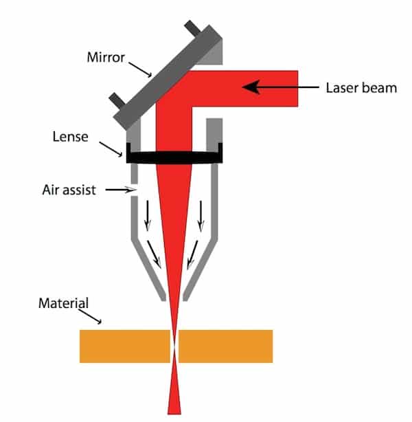
CO2 laser cutting employs a focusing lens to direct CO2 laser beams onto the surface of the material, causing it to melt.
Simultaneously, the molten material is removed by a coaxial flow of compressed gas, allowing the laser beams and material to move relative to each other along a defined path, resulting in a precise cut shape.
Since the 1970s, the development of CO2 lasers and numerical control technology has made CO2 laser cutting a highly advanced method for cutting sheet metal.
In the 1950s and 1960s, sheet metal cutting methods included:
- Oxyacetylene flame cutting for medium thickness sheets
- Cutting and slitting for thin sheets
- Stamping for mass production of complex components
- Vibratory cutting for individual parts
In the 1970s, to improve the quality of flame cuts, oxyethane precision flame cutting and plasma cutting became popular.
To reduce the manufacturing cycle time of large-scale stamping molds, CNC stamping and electroprocessing technology have been promoted.
Each type of cutting and slicing method has its own limitations and is used in specific industrial production applications.
Obvious advantages of CO2 laser cutting technology over other methods:
Good cutting quality:
- Small incision width (usually 0.1-0.5 mm)
- High precision (the overall hole center deviation is 0.1 to 0.4 mm, while the contour deviation is 0.1 to 0.5 mm)
- Good incision surface roughness (generally Ra 12.5-25 microns)
- Cut beams can be welded without additional processing.
High cutting speed:
For example, a 2KW laser with a cutting speed of 1.6m/min can cut carbon steel 8mm thick, while a cutting speed of 3.5m/min can be achieved on stainless steel 2mm thick. thickness. The laser cutting process results in a small area of thermal influence and minimal deformation.
Clean, safe and non-polluting:
The use of CO2 laser cutting significantly improves the working environment for operators. Although it may not surpass electroprocessing in terms of precision and surface roughness of cuts, and may have limitations in cut thickness compared to flame and plasma cutting, its advantages have led to the replacement of traditional cutting techniques, especially for cutting materials non-metallic. materials.
In China, since the 1990s and the development of the socialist market economy, there has been intense competition among enterprises, causing each enterprise to carefully choose advanced production technologies that meet its specific needs in order to improve the quality of product and production efficiency. As a result, CO2 laser cutting technology has seen rapid growth in China.
CO2 laser cutting industrial application
The first CO 2 laser cutting machine was invented in the 1970s. Over the past three decades, the machine has undergone continuous improvements as its fields of application have expanded.
At present, many domestic and international companies produce various types of CO2 laser cutting machines to meet market demand, including 2-D plate cutting machines, 3-D spatial curve cutting machines and pipe cutting machines .
Prominent foreign companies in this field include Trumpf (Germany), Prima (Italy), Bystronic (Switzerland), Amada and MAZAK (Japan), NTC (Japan) and HG Laser Lab (Australia).
According to the 2000 Annual Report of “Industrial Laser Solution”, a leading American laser industry magazine, total sales of laser cutting systems worldwide (mainly CO2 laser cutting systems) in 1999 were 3,325, totaling US$ 1.174 billion.
In China, nearly 100 CO 2 laser cutting machines are produced each year, totaling 150 million RMB, but their use in the country is relatively low compared with developed countries. In 2003, the number of CO2 laser cutting systems used in industrial production in China reached around 500, representing approximately 1.5% of the global total.
Two Main Types of CO 2 Laser Cutting System Buyer
There are two main types of organizations that use CO2 laser cutting technology: large and medium-sized manufacturing companies and processing stations.
Large and medium-sized industrial companies have strong economic and technical resources and require cutting and cutting for many of their materials.
Processing stations, also known as Job Shops abroad, specialize in providing laser processing services to third parties and do not have their own dominant products. These stations can meet the needs of small and medium-sized businesses and also play a role in promoting the early adoption of laser cutting technology.
In 1999, there were 2,700 laser processing stations in the United States, with 51% of them specializing in laser cutting.
In the 1980s, laser processing stations in China mainly focused on laser heat treatment. However, since the 1990s, the number of laser cutting and processing stations has increased.
As reforms in China's large and medium enterprise system continue and the country's economic strength grows, more and more companies are expected to adopt CO2 laser cutting technology.
Domestically, CO2 laser cutting is widely used to cut low carbon steel plates with a thickness of 12mm or less, stainless steel plates with a thickness of 6mm or less, and non-metallic materials with a thickness of 20mm or less. It has also been used in the automobile and aviation industries to cut three-dimensional spatial curves.
Currently, products suitable for CO2 laser cutting can be categorized into three groups:
- Sheet metal parts that are not economically or technically feasible to be manufactured through other methods, especially low carbon steel with complex shapes, small batch sizes and thicknesses less than 12 mm, and stainless steel with thicknesses less than 6 mm , in order to save mold manufacturing cost and time. Examples of such products include elevator components, elevator panels, machine tools and machine housings, electrical cabinets, distribution cabinets, textile machine parts, engineering machine parts, and large silicon steel sheets for motors.
- Stainless steel (generally less than 3mm thick) or non-metallic materials (generally less than 20mm thick) used in decoration, advertising and service industries, such as patterns in artistic photo albums, company logos, organizations, hotels and stores, shopping malls and fonts in Chinese and English in public places such as stations and docks.
- Special parts that require precise cutting, such as plates used in the packaging and printing industries. They require cutting 0.7 to 0.8 mm wide slots into 20 mm thick wooden templates, which are then used to cut a variety of printed packaging boxes. CO2 laser cutting is also used in oil screening pipes to prevent sediment from entering pumps and in cutting uniformly sized beams with widths less than 0.3 mm in alloy steel pipes with wall thicknesses of 6 to 9mm. The perforation diameter must be greater than 0.3mm, which is difficult to achieve, making CO2 laser cutting a popular solution for many companies.
In addition to the applications mentioned above, CO2 laser cutting is being used in a growing number of industries. For example, 3D laser cutting systems or industrial robots are used to cut spatial curves and specialized software has been developed to streamline the process from drawing to cutting parts.
Researchers are focused on improving production efficiency through the development of specialized cutting systems, material transport systems and linear motor drive systems. Cutting speeds have already exceeded 100 m/min.
In order to expand its use in the engineering machinery and shipbuilding industries, the cutting thickness of low carbon steel has been increased to more than 30 mm, and there is increasing interest in nitrogen gas cutting technology of low carbon steel to improve the quality of the plate incision.
Therefore, it is still very important for engineering technicians in China to expand the use of CO2 laser cutting and solve some technical problems in practical applications.
The parameters of the laser beam and the performance and precision of the machine and CNC system have a direct impact on the efficiency and quality of laser cutting. Key technologies, such as those required for parts with high cutting precision or thicker materials, must be mastered and solved.
Technologies must be mastered
1. Focus position control technology
One of the benefits of laser cutting is the high energy density of the beams, which is generally greater than 10W/cm2. The energy density is inversely proportional to 4/πd^2, so the diameter of the focal spot is kept as small as possible to produce a narrow slit.
The diameter of the focal spot is directly proportional to the focal depth of the lens, which means that the smaller the focal depth, the smaller the diameter of the focal spot. However, cutting can cause splashes and if the lens is too close to the workpiece it can be easily damaged.
Therefore, high-power CO2 laser cutting typically uses lenses with a focal length of 5″ to 7.5″ (127 to 190 mm). The actual diameter of the focal spot is between 0.1 and 0.4 mm.
The effective focal depth also depends on the diameter of the lens and the material being cut. For example, when cutting carbon steel with a 5″ lens, the focal depth should be within a range of +2% of the focal length, or about 5mm, for optimal cut quality.
To ensure the best cutting results, focus is essential and depends on the thickness of the material. For metal materials less than 6mm, the focus should be on the surface. For carbon steel thicker than 6mm, the focus must be above the surface. For stainless steel thicker than 6 mm, the focus must be below the surface, but the exact size must be determined through experimentation.
Three simple methods to locate the focus position in industrial production:
There are three methods to determine the focus of the CO2 laser cutting machine:
- Printing method: In this method, the cutting head is moved from top to bottom and the laser beam is printed on a plastic plate. The smallest diameter of the beam indicates the focus.
- Inclined plate method: In this method, the plastic plate is placed at a certain inclination with respect to the vertical axis and moved horizontally. The smallest laser beam indicates the location of the focus.
- Blue spark method: This method involves removing the nozzle, blowing air, and hitting a stainless steel plate with a pulsed laser. The cutting head is moved from top to bottom until a blue spark reaches its limit, which indicates the location of the focus.
For flying light path cutting machines, determining the focus is more complex, as the divergence angle of the laser beams causes differences in the distance between the near end and the distal end, leading to differences in the beam size before focusing. The larger the diameter of the incident beam, the smaller the focal spot.
To minimize variation in focal spot size caused by changes in beam size before focusing, laser cutting system manufacturers offer some special devices for users to choose from:
- Parallel Light Tube: This is a commonly used method that involves adding a parallel light tube at the output of the CO2 laser beam to expand the beams. This increases the diameter of the beam and decreases the angle of divergence, making the sizes of the near and far ends of the beam more similar before focusing.
- Movable Lens: Another option is to add a separate movable lens to the cutting head that is independent of the Z axis and controls the distance from the nozzle to the material surface. When the bench or light shaft moves, the beam also moves simultaneously from the near end to the far end of the F-axis, ensuring that the beam focal spot diameter remains consistent throughout the processing area.
- Water pressure control: Some systems control the water pressure of the focusing lens, which is typically a metal reflection focusing system. When the focusing beam size decreases and the focal spot diameter increases before focusing, the water pressure is automatically adjusted, changing the focal curvature and decreasing the focal spot diameter.
- Optical path compensation: A system that adds optical path compensation in the x and y directions of the flight path cutting machine. This means that the optical compensation path is shortened when the optical distance at the distal end of the cut increases, and lengthened when the optical distance at the near end of the cut decreases, keeping the optical path distance consistent.
2. Cutting Drilling Technologies
Laser cutting technology, except in a few cases, typically requires drilling a small hole in the material. In the past, laser stamping machines first used a punch to make a hole and then a laser to cut the hole. For non-stamping laser cutting machines, there are two basic drilling methods:
- Explosion drilling: After continuous laser exposure, a hole forms in the center of the material, which is quickly removed by a coaxial flow of oxygen, forming a hole. The average hole diameter is approximately half the thickness of the material, so for thicker sheets, shot blasting creates non-circular holes with a larger diameter, making it unsuitable for parts with high requirements (such as oil screening pipes), but suitable for waste materials. The oxygen pressure used in drilling is the same as in cutting, which causes a lot of spatter.
- Pulse drilling: Full-power pulse lasers cause some materials to melt or vaporize, typically using oxygen or nitrogen as an auxiliary gas to reduce hole expansion caused by exothermic oxidation. The gas pressure is lower than the oxygen pressure used in cutting, and each laser pulse produces only small particles that are ejected at depth, making it take a few seconds to drill through thicker plates. Once drilling is complete, the auxiliary gas is immediately replaced with oxygen for cutting. This results in a smaller drilling diameter and better drilling quality compared to blast drilling.
For pulse drilling, the laser used must not only have high output power, but also high time and space characteristics of the beams. The pulse drilling process must also have a reliable gas path control system to control the gas type, gas pressure switching and drilling time. The transition from pulsed drilling to continuous material cutting must also be emphasized to obtain high-quality cuts.
In industrial production, it is more practical to change the average laser power, such as changing the pulse width, frequency, or both simultaneously. The third method proved to have the best effect.
3. Nozzle Design and Airflow Control Technique
When cutting steel with a laser, the oxygen and laser beam are directed through a nozzle into the material to form a flow. For cutting to be effective, the air flow needs to be large and fast to produce sufficient oxidation and exothermic reaction in the cut material. Furthermore, the air flow must have sufficient momentum to remove the molten material. Nozzle design and airflow control, such as pressure and position of the nozzle and workpiece, are crucial factors that affect cut quality.
Currently, the nozzles used in laser cutting have a simple design, consisting of a cone with a small hole at the top. Nozzle design is usually done through experiments and derivation methods. However, because the nozzle is usually made of copper and is small and vulnerable, it requires frequent replacement and is typically not considered in fluid mechanics calculations and analyses.
When in use, gas with pressure Pn enters the nozzle and creates pressure in the nozzle. The gas leaves the nozzle and reaches the surface of the part after a certain distance, forming a cutting pressure Pc. Finally, the gas expands to form atmospheric pressure Pa. Research has shown that as Pn increases, airflow velocity and Pc also increase.
The formula for calculating airflow velocity is:
V = 8.2d^2 (Pg + 1)
where:
V = air flow speed in L/min
d = nozzle diameter in mm
Pg = nozzle pressure (surface pressure) in bar
When the nozzle pressure exceeds a certain value, the airflow can change from subsonic to supersonic and become a normal oblique shock wave. The limit value depends on the relationship between the nozzle pressure (Pn) and atmospheric pressure (Pa) and the degree of freedom (n) of the gas molecules. For example, when n=5 for oxygen and air, the Pn limit is 1.89 bar.
If the nozzle pressure is higher, i.e. Pn/Pa > 4 bar, the normal oblique airflow shock wave can transform into a normal shock, causing the cutting pressure (Pc) to decrease, the speed airflow decreases and a vortex forms on the surface of the part, which weakens the effect of airflow in removing molten material and affects cutting speed.
To avoid this, oxygen nozzle pressure is often kept below 3 bar when using a nozzle with a cone and a small hole at the top.
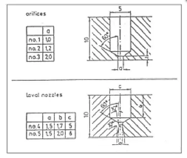
To increase the speed of laser cutting, a converging-diverging nozzle called the Laval nozzle was designed based on aerodynamic principles. This nozzle increases pressure without causing normal shock waves. The nozzle structure is shown in Figure 4 to facilitate manufacturing.
The laser center at the University of Hanover in Germany conducted experiments pairing a 500 W CO2 laser (with a focal length of 2.5) with a conical nozzle and a Laval nozzle. The results of the experiments are represented in the figures, which show the relationship between surface roughness (Rz) and cutting speed (Vc) for nozzles nº 2, nº 4 and nº 5 under different oxygen pressures.
As shown in the figures, when the pressure (Pn) is 400 Kpa (or 4 bar), the cutting speed of hole No. 2 nozzle reaches only 2.75 m/min (for a 2 mm thick carbon steel plate ). However, at Pn of 500 Kpa or 600 Kpa, the cutting speed of Laval no. 4 and no. 5 nozzles reaches 3.5 m/min and 5.5 m/min, respectively.
It is important to note that the cutting pressure (Pc) depends on the distance between the part and the nozzle. The oblique shock wave is repeatedly reflected at the airflow boundary, causing the cut-off pressure to fluctuate periodically.
The first high cutting pressure zone is located close to the nozzle exit, with the distance between the workpiece surface and the nozzle exit being approximately 0.5 to 1.5 mm. This results in high and stable cutting pressure (Pc), making it a widely used parameter in industrial production.
The second high cutting pressure zone is approximately 3 to 3.5 mm away from the nozzle exit and also presents high cutting pressure, contributing to good cutting results and protecting the lens, thus improving its useful life.
However, other high shear pressure zones in the curves are too far from the nozzle exit to align with the focused beam.
In conclusion, CO2 laser cutting technology is being increasingly used in industrial production in China. Abroad, efforts are being made to study technologies and cutting equipment that can achieve higher cutting speeds and handle thicker steel sheets.
To meet the growing demands for high-quality industrial production and increased efficiency, it is important to focus on resolving fundamental technological issues and implementing quality standards, making this new technology more widely adopted in our country.