1. What is sheet metal laser cutting machine?
1. Definition of sheet metal laser cutting machine
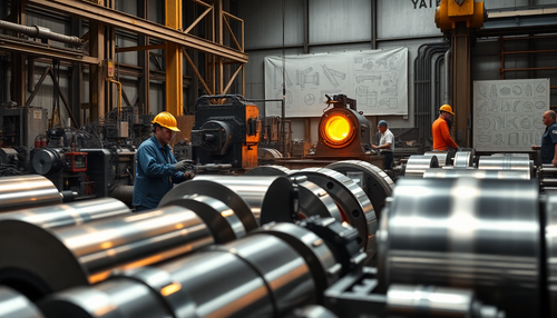
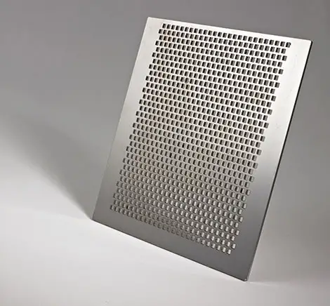
(1) It is mainly used to cut the plate into the required shape of the workpiece.
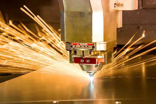
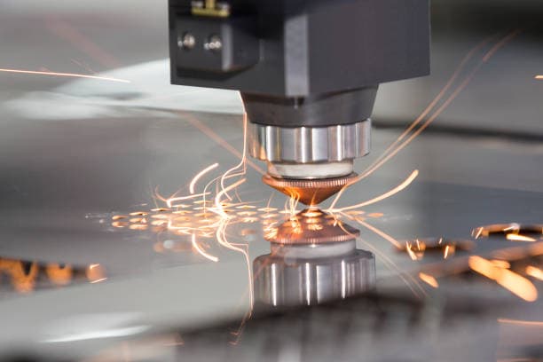
(2) Equipment that uses the thermal energy of a laser beam to cut is obtained by melting and evaporating the workpiece when the laser beam is directed to the surface. This results in cutting and engraving of the workpiece.

Laser cutting has several advantages, including high precision, fast cutting speed, flexibility in terms of cutting patterns, automatic typesetting, material saving, smooth cutting edges and low processing cost. As a result, it is gradually improving or replacing traditional cutting equipment.
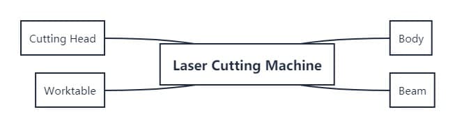
2. Main components of sheet metal laser cutting machine
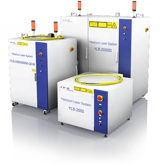
(1) Laser
Lasers can be divided into:
- CO2 laser
- Nd:YAG laser
- Semiconductor laser
- Disk laser
- fiber laser
The fiber laser produces a laser that is not only easy to control but also has good directivity, monochromaticity and coherence. As a result, it is widely used in mechanical manufacturing and sheet metal processing.
(2) Main machine
There are two types of relative movement between the cutting head and the bench:
(1) Only the cutting head moves during the cutting process, while the bench remains stationary.
(2) Only the bench moves during the cutting process, while the cutting head remains fixed.
Other components of a cutting system include:
(3) Refrigeration system, which uses water for cooling.
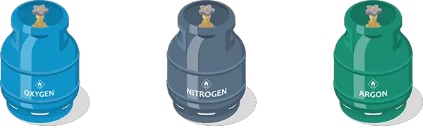
(4) Air supply system, which may use bottled gas (oxygen, ammonia) or compressed air (air compressor, filter, dryer).
(5) Power supply, which requires a three-phase voltage stability of ±5% and a power imbalance of no more than 2.5% (calculated as the highest three-phase voltage minus the lowest three-phase voltage, divided by the average voltage of the three phases).
1: Air cutoff requirements
- High performance screw compressor is selected.
- Compressor working pressure: 12 MPa.
- Air compressor:
Compressor air exhaust volume: 2.0 m³/min.
2: Dryer:
- High performance refrigerated air dryer is selected.
- Dryer processing capacity: 2.0 m³/min.
- Dryer inlet pressure: 1.2 MPa.
3: Filter:
- High performance multi-stage precision filter.
- The filtering level is divided into four levels: QPSC level.
- Self-configurable filter accuracy:
- 0.3µm x 1 piece
- 0.01 µm x 1 piece
- 0.001 µm x 2 pieces
(6) Control System:
Light guide focusing system:
According to the performance requirements of the part to be processed, the beam is amplified, shaped and focused to act on the processing part. The device from the laser exit window to the workpiece to be processed is called the light guide focusing system.
Laser processing system (Cypcut laser cutting system):
The laser processing system mainly includes the machine base, the bench that can move within the three-dimensional coordinate range, and the electromechanical control system. With the advancement of electronic technology, many laser processing systems use computers to control the movement of the worktable and achieve continuous laser processing.
Main technical parameters of CF3015 sheet metal cutting machine:
- Cutting area: 3,005 mm x 1,505 mm
- Z axis travel: 110 mm
- Machine tool accuracy (according to VDL/DGQ3441): ±0.1 mm/m
- Repeatability: ±0.05mm
- Maximum Axial Acceleration: 2,000mm/s²
- Maximum cutting speed: 20m/min
- Machine weight: Approximately 3.5T
- Color standard: NCS S 0585-Y80R; NCS S7020-R60
- Maximum bench bearing capacity: 250 kg (3,000 x 1,500 x 6 mm)
Machine tool accuracy VDL/DGQ3441 measuring length 1 meter.
Note: Cutting accuracy depends on sheet thickness, sheet tension and pulling force.
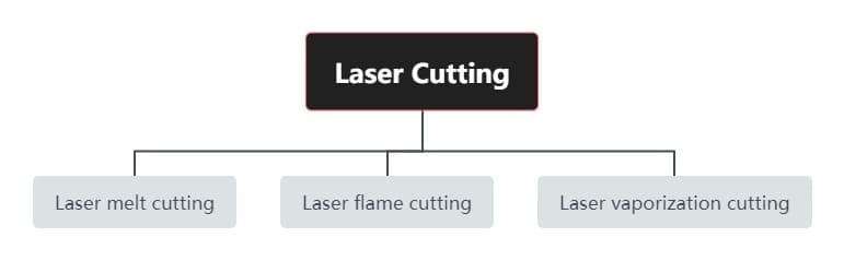
2. Laser cutting method
Laser cutting can be classified into three types: laser metal cutting, laser flame cutting and laser vaporization cutting.

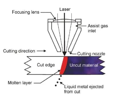
2.1 Laser fusion cutting
In laser fusion cutting, after the part is locally melted, the molten material is expelled by a flow of air. This process is known as laser fusion cutting because the material transfer occurs only in the liquid state. The laser beam, combined with high-purity inert cutting gas, causes the molten material to flow out of the cut, while the gas itself does not participate in the cutting.
The maximum cutting speed increases with increasing laser power and decreases almost proportionally with increasing plate thickness and material melting temperature. When the laser power is constant, the limiting factor is the air pressure at the cut and the thermal conductivity of the material.
Laser fusion cutting can produce oxidation-free cuts for iron materials and titanium metals.
2.2 Laser flame cutting
The difference between laser flame cutting and laser fusion cutting is that oxygen is used as the cutting gas in laser flame cutting. A chemical reaction is generated between the oxygen and the heated metal, which heats the material even more. This results in a higher cutting rate for structural steel of the same thickness compared to laser fusion cutting.
However, laser flame cutting may have worse carving quality than laser fusion cutting. It can produce wider cuts, roughness, increased heat affected zone and poor edge quality. Laser cutting is not suitable for machining precision models and sharp corners as there is a risk of burns.
A pulsed mode laser can be used to reduce the thermal effect. The cutting speed is determined by the laser power used.
See too:
- Laser cutting thickness and speed chart
When the laser power is constant, the limiting factor in laser flame cutting is the oxygen supply and thermal conductivity of the material.
2.3 Laser gasification cutting
In the laser gasification cutting process, a high-power laser is used to cause the material to gasify at the cutting point. This cutting method is only suitable for applications where the presence of molten material must be avoided and is therefore limited to a small range of iron-based alloys.
The maximum cutting speed is determined by the gasification temperature of the material and is inversely proportional to the sheet thickness. To prevent material vapor from condensing on the slit walls, the thickness of the material must not exceed the diameter of the laser beam.
The laser power density required for this process is significant, exceeding 108W/ cm2 and depends on the material being cut, the depth of cut and the position of the laser beam focus.
When the plate thickness is constant and there is sufficient laser power, the maximum cutting speed is limited by the speed of the gas jet.
Laser cutting technology
Several important technologies in laser cutting are a combination of light, machinery, and electricity.
Laser beam parameters, machine performance and precision, and numerical control system directly impact cutting efficiency and quality.
Focus position control technology: One of the advantages of laser cutting is the high beam energy density. Currently, a focal length ranging from 120 to 200 mm is widely used in industrial fiber laser cutting applications.
Laser Drilling Technology: With any thermal cutting technology, except in rare cases where it may start at the edge of the board, a small hole in the board is usually required. There are two main methods for laser cutting machines: sandblasting and progressive drilling.
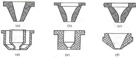
Nozzle Design and Airflow Control Technology: Currently, the nozzle used for laser cutting has a simple structure, consisting of a conical hole with a small circular hole at the end. Design is often determined by trial and error.
Laser cutting process analysis
Laser cutting is a process that involves melting and vaporization.
There are many factors that can affect the quality of the cut.
See too:
9 Factors That Affect Laser Cutting Quality
In addition to hardware factors such as machine tool and processing materials, software factors also play a significant role in affecting the quality of the laser cutting process.
Computer-aided process design is the fundamental approach to studying the impact of these software factors on the quality of the cutting process. That includes:
① Puncture point selection: The position of the puncture point is determined based on the specific situation.
② Auxiliary cutting path setting:
③ Laser beam beam compensation and empty stroke processing:
④ Board layout optimization: Board utilization rate is improved by saving materials.
⑤ Part set path selection:
⑥ Consideration of the influence of processing factor: The path is selected by taking into account the effects of factors such as thermal deformation.
3. Laser cutting process

The laser cutting process “refers to the interaction between the laser beam, the cutting gas and the workpiece.
3.1 Laser cutting process
The laser cutting process takes place before the actual cutting. The laser heats the part to the temperature necessary to melt and vaporize the material. The cutting plane is composed of an almost vertical plane that is heated and melted by the absorbed laser radiation.
In laser cutting, the fusion zone is further heated by the flow of oxygen entering the slit, reaching a temperature close to the boiling point. The resulting gasification removes the material, and the liquefied material is expelled from the bottom of the part through the use of process gas. In laser fusion cutting, the liquefied material is expelled with the gas, which also protects the gap from oxidation.
The continuous fusion zone moves along the cutting direction, producing a continuous crack. Many critical aspects of the laser cutting process occur in this area, and analyzing these activities can provide valuable information about laser cutting. This information can be used to calculate cutting speed and explain the formation of traction line features.
3.2 Material characteristics
The result of cutting operations on a part may result in a clean cut or, on the other hand, a rough or burnt edge.
The main factors that affect cut quality include:
- League Composition
The composition of the alloy can affect the strength, specific gravity, weldability, oxidation resistance and acidity of the material to a certain extent. Some crucial elements in ferroalloy materials include carbon, chromium, nickel, magnesium and zinc. The higher the carbon content, the more challenging it becomes to cut the material (0.8% being considered the critical value). Some types of carbon steel suitable for laser cutting include Q235 and SW22 (low-carbon, low-silicon aluminum dead steel).
- Microstructure of Materials
In general, the finer the particle size of the constituent material, the better the quality of the cutting edge.
- Surface quality and roughness
If the surface has rusty areas or layers of oxide, the cut profile will be irregular and will have many damaged spots. To cut corrugated sheet metal, select the maximum thickness cutting parameter.
- Surface treatment
Common surface treatments include galvanizing, focused galvanizing, painting, anodizing, or covering with a layer of plastic film. Zinc-treated sheet metal is subject to slag buildup at the edges. For painted sheets, the quality of the cut will depend on the composition of the coating.
How to process painting materials:
The first pass involves selecting a set of low power parameters (for etching) to pre-burn and mark the treated surface. The second pass involves selecting a set of parameters for cutting the material.
Plates with layered material coating are highly suitable for laser cutting. To ensure the correct functioning of the capacitive detection and for better adhesion of the layered coating (to avoid the formation of bubbles), the layered edge must always be positioned on the top of the cutting piece.
- Beam reflection
The way the light beam is reflected from the surface of the part depends on the underlying material, surface roughness and treatment.
See too:
- Surface roughness: the comprehensive analysis
Some aluminum, copper and brass alloys have high reflectivity characteristics and are not suitable for cutting with a fiber laser cutting machine.
See too:
- The Ultimate Guide to Fiber Laser Cutting Machine
- Thermal conductivity
Materials with low thermal conductivity require less energy to weld than materials with high thermal conductivity. For example, chromium-nickel alloy steel requires less energy than structural steel and generates less heat that is absorbed during processing. On the other hand, materials such as copper, aluminum and brass absorb most of the heat generated by laser light. As the heat is conducted away from the target point of the beam, it becomes more difficult to fuse the material in the heat-affected zone.
- Heat affected zone
Laser flame cutting and laser fusion cutting can result in variations in the material near the edge of the cut material. Quenching in the heat-affected zone is reduced when processing low-carbon steel or oxygen-free steel. However, for high carbon steel (60#), the edge area becomes harder.
- Fusion point
- Hot melt
- Gasification temperature
3.3 Processability of different materials
S structural steel
When cutting material with oxygen, best results will be obtained using a continuous mode laser. The small curve control system adjusts the laser power according to the spindle feed rate. When oxygen is used as the processing gas, the cutting edge will be slightly oxidized.
For sheets with a thickness of less than 3 mm, ammonia gas can be used for high pressure cutting, resulting in a non-oxidized cutting edge.
Complex contours and small holes with a diameter smaller than the material thickness should be cut in pulsed mode to avoid cutting sharp corners. The higher the carbon content, the easier it is to season the cutting edge and the more likely it is that the edge will be burned. Plates with high alloy content are more difficult to cut than those with low alloy content.
An oxidized or sandblasted surface will result in poor cutting quality and residual heat on the board surface can have a negative impact on cutting results. To eliminate tension, only secondary treated steel plates should be cut. Impurities in steel molten under boiling conditions significantly affect cutting results.
For clean surface cuts in structural steel, the following tips should be followed:
- S ≤ 0.04%: preferred, laser processing produces good results.
- Si < 0.25%: in some cases slightly lower incisions can be obtained.
- Si > 0.25%: not suitable for laser cutting and may result in worse or inconsistent results.
S stainless steel
Cutting stainless steel requires the following:
- Oxygen can be used when oxidation of the edges does not matter.
- Nitrogen can be used to obtain oxidation- and burr-free edges, with no additional treatment required. With high laser power and high pressure nitrogen, the cutting speed can be equivalent to or exceed that of oxygen.
- To cut stainless steel with nitrogen without burrs, it is necessary to adjust the focus position. By resetting the focus position and reducing the speed, a clean cut can be achieved, although small burrs cannot be avoided.
For stainless steel, the following must be considered:
- Oxygen cutting: for sheets thicker than 3mm, reduce the feeding speed and adopt a progressive mode for drilling.
Laser cutting method:
- Continuous Cutting (also known as CW – Continuous Wave Cutting Method): This method cuts by continuously generating an oscillation output. It is the method with the highest cutting speed for cutting low carbon steel.
- Pulse cut method: This method cuts intermittently generating the oscillation output. By reducing heat input into the material, pulsed cutting can produce good cut quality and dimensional accuracy. When performing pulse cutting, the pulse frequency must be set. Pulse frequency refers to turning the laser beam on and off several times per second, expressed in Hz.
- The advantage of continuous cutting is speed, but the cutting quality is not that good. Excessive heat input from continuous heat input into the material affects cutting quality and dimensional accuracy. On the other hand, pulsed cutting has good cutting quality, but is slower than continuous cutting. For example, with a 500W laser generator, the CW cutting speed of 6mm low carbon steel is 800mm/min, but the pulse cutting is only 600mm/min. The speed difference increases with thinner plates. Generally, if the thickness of the steel plate exceeds 3mm, CW cutting is not applicable.
Choosing the cutting mode is usually done when creating a program or changing machine parameters.
3.4 Gas parameters
Gas parameters include:
- Type of gas;
- Pressure;
- Nozzle diameter and geometry.
Air pressure and nozzle geometry play a role in determining edge roughness and burr generation. Processing gas consumption depends on nozzle diameter and air pressure. Cutting air pressure below 1.0 MP is considered low pressure, while 1.5 MP is considered high pressure.
The most commonly used cutting nozzle has a circular, cone-shaped opening. It is important to keep the distance between the nozzle and the part surface as small as possible to maximize the quality of the gas impacting the crack wall. A spacing between 0.5 and 1.5 is often used.
4. Laser processing
4.1 Laser drilling
The value of the drilling parameter is different from that of cutting.
Drilling in continuous mode
- Advantages: fast drilling.
- Disadvantage: a drilling well is generated.
Pulse mode drilling
- Advantages: small through holes.
- Disadvantages: time consuming
Note: Plate thickness (mm) approximately corresponds to drilling time(s).
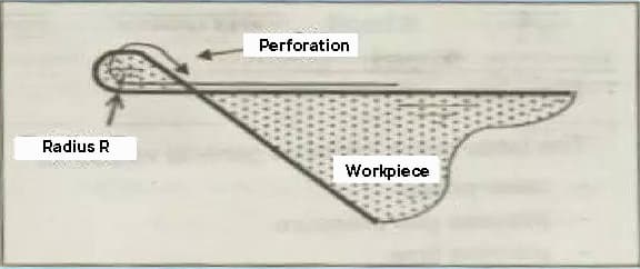
4.2 Feed and overcut
CW mode is commonly used for drilling, which is faster but produces a larger hole than pulse drilling. For this reason, the position of the cut hole is normally placed outside the contour. The distance between the perforation and the actual contour is known as the main portion.
Irregularity at the edge of the notch in the workpiece may indicate a change in the focus of the weak light beam from the end of the initial cut piece to the contour. The user should place the conductive part on the ideal extension line on one side of the geometric unit as far as possible.
When cutting small internal contours on the surface, it is important to allow the heat generated during the drilling process to dissipate before starting the cut. Avoid placing the perforations in a narrow area and position them at a large angle to the contour, which promotes heat dissipation.
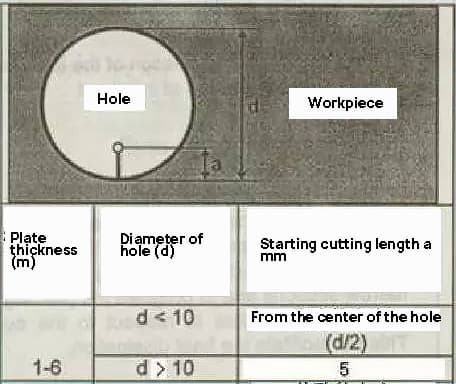
The length of the lead depends on the thickness of the plate and the diameter of the hole.
4.3 Corner processing
Obtuse angle machining with radius
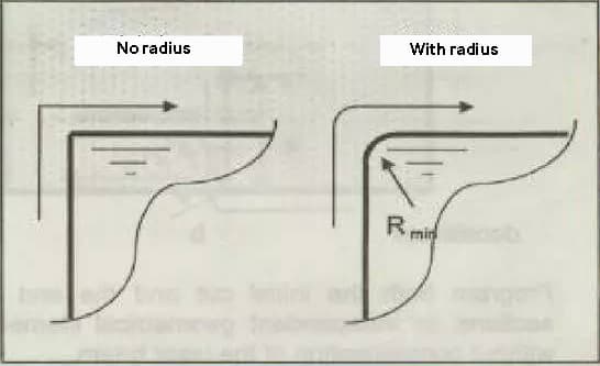
Whenever possible, avoid throwing at an angle without a radius.
The corner with radius has the following advantages compared to the corner without radius:
- The dynamic performance of shaft movement is better;
- Reduction of the heat-affected zone;
- Burrs are less generated.
Ideal rounding radius:
R optimal = plate thickness (mm) divided by 10, but not less than 1mm;
When no corner radius is required on the inner plate, the maximum radius is:
Edge R = half the width of the incision.
With this beam, a radiusless corner can still be generated and now the axis moves dynamically:

For high-speed cutting of thin sheets, the use of hole technology is recommended. This solution has the following advantages:
- The axis changes direction through an acute angle in a fixed direction.
- The part is cut at a constant speed.
- The thermal influence on the corner is reduced.
Evaluate laser cut incisions
| Structural steel: cutting with O 2 | ||
| Defect | Possible Causes: | Settlement terms |
No burrs, consistent line of pull 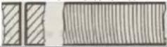
|
Adequate powerAdequate power rate | |
The draw line at the bottom has a large offset, and the notch at the bottom is wider. 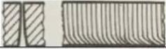
|
Feed rate too high Laser power too low Air pressure too low Focus too high | Reduce feed rateIncrease laser powerIncrease air pressureDecrease focus |
The burr on the lower surface is similar to slag, in the form of droplets and easy to remove. 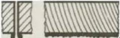
|
Feed rate too high Air pressure too low Focus too high | Reduce feed rateIncrease air pressureDecrease focus |
The metal burrs connected together can be removed as a whole. 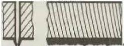
|
The focus is too high. | Lower the focus. |
Metal burrs on the bottom surface are difficult to remove 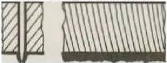
|
Feed rate too highAir pressure is too lowImpure gasFocus is too high. | Reduce feed rateIncrease air pressureUse purer gasDecrease focus |
There are burrs only on one side 
|
Incorrect mouth alignment. Defective nozzle mouth | Centering nozzleReplace nozzle |
| Structural steel: cutting with O 2 | ||
| Defect | Possible Causes: | Delete |
Material unloaded from above 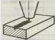
|
Power too low, feed rate too high | In this case, press the pause button immediately to prevent the slag from splashing onto the focusing lens.And then increase the power;Reduce the feed rate. |
Inclined surface cut, good on both sides, bad on both sides. 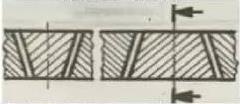
|
Inadequate, incorrect or defective polarization mirror; the polarizing mirror is installed in the position of the deflection mirror | Check the polarizing mirror; Check the deflection mirror. |
Blue plasma, uncut workpiece 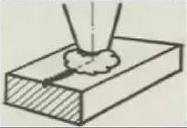
|
Process gas error (N 2 );Feed rate is too high; Very low power | In this case, press the pause button immediately to prevent slag from splashing onto the focusing lens;Using oxygen as the processing gas; Reduce the feeding rate; Increase power |
Inaccurate cutting surface 
|
The air pressure is too high; The nozzle is damaged; The nozzle diameter is too large; The material is not good. | Reduce air pressure;Replace the nozzle;Install appropriate nozzles;Use a material with a smooth and uniform surface. |
There are no burrs and the pull line is inclined; The incision becomes narrower at the bottom. 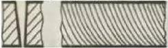
|
Feed rate too high | Reduce the feed rate. |
Crater generation 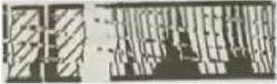
|
The air pressure is too high; The feed rate is very low; The focus is too high; There is rust on the surface of the board; The processed part is overheated; The material is not pure. | Reduce air pressure;Increase feed rate;Lower focus;Use better quality materials. |
Very rough cutting surface 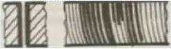
|
The focus is too high; The air pressure is too high; Feed rate is too low; The material is very hot. | Lower the focus;Reduce air pressure;Increase the feed rate;Cool the material. |
| Stainless steel: cutting with N 2 high pressure | ||
| Defect | Possible Causes: | Settlement terms |
Producing fine and regular drop-shaped burrs; 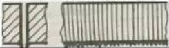
|
Focus is too low; The feed rate is very high. | Increase focus; Reduce the feed rate. |
Irregular filamentous burrs grow on both sides, and the surface of the large plates changes color. 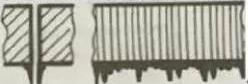
|
The feed rate is very low; The focus is too high; The air pressure is too low; The material is very hot. | Increase the feeding rate; Decreasing focus; Increase air pressure; Cooling material. |
Irregular burr growing only on one side of the cutting edge 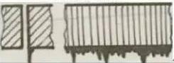
|
The nozzle is not centered; The focus is too high; The air pressure is too low and the speed is too low. | Centralizing nozzle; Decreasing focus; Increase air pressure; Increase speed. |
| Tip yellowing | The atmosphere contains oxygen impurities. | Use good quality nitrogen. |
The plasma is generated in a straight section. 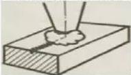
|
The feed rate is very high. | If this happens, press temporarily. |
| Generating plasma on the surface in a straight line | Feed rate is too high; The power is too low; The focus is too low. | In this case, press the pause button immediately to prevent slag from splashing onto the focus lens;Reduce the shooting speed;Increase the power;Increase the focus. |
| Beam scattering | The feed rate is very high; The power is too low; The focus is too low. | Reduce the feeding rate; Increase power; increase focus. |
| Generate plasma on the corner | The angle tolerance is very high; Modulation is very high; The acceleration is very high. | Reduce angle tolerance; reduce modulation or acceleration. |
| The beam diverges at the beginning | Acceleration is too high; Focus is too low; Molten material has not been discharged | Reduce acceleration; increase focus and drill the circular hole. |
| rough incision | The nozzle is damaged; The lens is dirty. | Replace the nozzle; clean the lens if necessary. |
Material unloaded from above 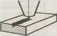
|
Power too lowFeed rate too highAir pressure is too high | In this case, press the pause button immediately to prevent molten tears from splashing onto the focusing lens Increase power and decrease feed rate Reduce air pressure |
5 . Sheet Metal Laser Cutting Precautions

To obtain the best processing quality, follow the following instructions:
- Precision adjustment machine tool;
- Maintain according to the maintenance plan;
- Processing in accordance with the above requirements;
- The surface of the workpiece must be free from rust or scale (pickled or smooth)
- The parameters correspond to the material and board specifications;
- Predefined interrelated parameters.
When a reduction in machining quality is observed, check the following factors:
- Parameters;
- Machining head;
- Beam path;
- Laser;
Do not modify the default parameters set when purchasing the laser cutting machine;
See too:
- How to choose fiber laser cutting machine? (Buyer's Guide)
To optimize the parameters, create a new directory for them. If processing quality deteriorates, compare the machine's default parameters with the optimized parameters to determine whether significant changes have been made.
The surface quality of materials greatly affects the quality of laser cutting. Raw materials must be protected from rust and dirt. If the surface is rusty, dirty or uneven, the material must be treated before cutting on the laser cutting machine.
To obtain the best cutting quality, the operator must follow these principles:
- Use default cutting parameters based on material thickness and type.
- When the cutting quality decreases, adjust using the default cutting parameters.
- The main parameters to be adjusted are laser power, gas pressure, focus position and cutting speed.
- Instead of rewriting the default parameter files, the operator should create his own parameter files and parameter file directory to continuously develop his experience.
Low light level operation mode includes continuous mode and pulse mode. Continuous mode is used for normal cutting, while pulsed mode is used for processing small holes and perforations smaller than the thickness of the material.
To cut parts that will be reused, pulsed drilling can be performed on the graphic contour. Continuous mode drilling is generally used for faster cutting, but results in a larger hole compared to pulsed drilling.
Heat dissipation before and after drilling is crucial when cutting small materials. Avoid connecting the cutting line with narrow parts of the workpiece and make sure there is a sufficient included angle with the figure to allow heat dissipation.
The maximum cutting size of the laser cutting machine is 3000 x 1500 mm. The maximum cutting capacity of a 500W fiber laser cutting machine is 6mm for carbon steel and 4mm for stainless steel.
See too:
- How to select the power of fiber laser cutting machine?
The smallest hole that can be drilled must be larger in diameter than the thickness of the plate.
Safety regulations for operating the laser cutting machine:
- Comply with general safety standards for cutting machines.
- Start the laser by following the proper laser startup procedure.
- The operator must be trained and familiar with the structure and performance of the equipment and have a good knowledge of the operating system.
- Use the necessary personal protective equipment.
See too:
- Radiation from laser cutting machine (it is harmful to human body)
- Do not process a material unless you are sure it can be irradiated or heated by the laser to avoid the potential danger of smoke and vapor.
- The operator must not leave the machine unattended while it is in operation. If it is necessary to leave, the machine must be turned off or the power switch must be turned off.
- Keep a fire extinguisher within reach. Turn off the laser or shutter when not in use. Do not place paper, cloth or other flammable materials near the unprotected laser beam.
- If there is a problem during processing, the machine must be shut down immediately to solve the problem or report it to the relevant personnel.
- Keep the laser, bed and surrounding area clean, organized and free from oil pollution. Store workpieces, plates and waste as needed.
- When using gas cylinders, avoid crushing the welding wires to avoid leaks. Follow regulations for using and transporting gas cylinders. Do not expose the gas cylinder to the sun or heat sources. Stand next to the cylinder mouth when opening the valve.
- Observe high voltage safety regulations during maintenance. Perform maintenance every 40 hours of operation or weekly, and every 1000 hours of operation or every six months, following the rules and procedures.
- After turning on the machine, manually run the X and Y axes at low speed to check whether there are any abnormalities.
- Before using a new part program, perform a test run and check its performance.
- During operation, be aware of the machine's movements to avoid accidents due to the cutting machine moving outside its operating range or collision.
See too:
- 13 Laser Cutting Machine Maintenance Checklist
Conclusion
Through the above training content, I think you have a deeper understanding of sheet metal laser cutting, which will definitely be helpful to you.
If you still have other questions about laser cutting sheet metal, leave a message in the comments area.