Overview
Using powder materials for 3D printing, the SLS process mentioned above is relatively expensive due to the use of lasers. However, employing a binding agent to adhere the powder particles and layer them to form shapes is theoretically correct. On April 20, 1993, Professor Emanuel Sachs and his team at MIT obtained a US patent for “Three-Dimensional Printing Techniques”, known as 3DP.
The invention was inspired by the inkjet printers widespread at the time, replacing the ink in the cartridges with a liquid binder. By extruding this binder onto a layer of loose powder with the print head, three-dimensional objects could be printed. Similarly, using primary color binders and precise digital color matching, full-color powder printing was possible, similar to inkjet color printing on paper.
This 3D printing process closely resembles conventional printers and its patent title, “3D printing”, is straightforward and easy to understand. Before this, 3D printing technology was known as rapid prototyping. Since then, the term “3D printing” has gained popularity, and all rapid prototyping technologies are commonly referred to as 3D printing, with the devices themselves being called 3D printers.
In 2012, the American Society for Testing and Materials (ASTM) defined this 3D printing process as “Binder Jetting” in its additive manufacturing terminology standard (ASTM F2792-12a).
In theory, the binder blasting process can be used to 3D print various powder materials such as ceramics, metals, plaster, plastics and sand. In 1995, Z Corporation was created under license from MIT, focusing on commercializing gypsum powder binder blasting.
Since 1997, they have released a series of binding jet printers, including the entry-level monochrome ZPrinter 310 Plus and, in 2005, the world's first color 3D printer, the Spectrum Z510, as shown in Figure 5-31 with the printer colored and printed models. This marked a significant step in the evolution of 3D printing, making it vibrant and colorful. In 2012, Z Corporation was acquired by 3D Systems, which further developed the Color-Jet series of printers.
Specifications for the Color-Jet series currently sold on the 3D Systems website are shown in Table 5-1.

Table 5-1: 3D Systems official specifications for Color-Jet series printers.
| Model | ProJet260C | ProJet360 | ProJet 460Plus | ProJet660Pro | ProJet860Pro |
| Color | Basic Color (CMY) | Monochrome (white) | Basic Color (CMY) | Colors (CMYK) | Basic Color (CMY) |
| Layer thickness/mm | 0.1 | 0.1 | 0.1 | 0.1 | 0.1 |
| Resolution/dpi | 300×450 | 300×450 | 300×450 | 600×540 | 600×540 |
| Print Dimensions/mm | 236×185×127 | 203×254×203 | 203×254×203 | 254×381×203 | 508×381×229 |
| Print speed/(mm/h) | 20 | 20 | 23 | 28 | 5~15 |
| Number of print heads | 2 (HP57+HP11) | 1 (HP11) | 2(HPS7+HP11) | 5(HP11) | 5(HP11) |
| Number of nozzles | 604 | 304 | 604 | 1520 | 1520 |
In 1996, Extrude Hone Corporation received a license from MIT to research and commercialize metal powder material formed by binder blasting, introducing the world's first metal powder binder blasting device, ProMetal RTS-300, in 1997.
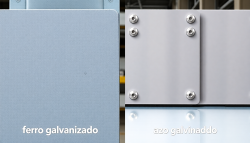
In 2003, ExOne Company emerged from Extrude Hone, focusing exclusively on the 3D printing industry, later launching the world's first sandstone 3D printer, the S15. Since then, ExOne has specialized in binder blasting of metal and sandstone materials, gradually becoming a leader in 3DP technology. Figure 5-32 shows the ExOne Innovent+ printer and some of the metal models printed by the company.

Founded in 1999, the German company Voxeljet also obtained a license from MIT and has been dedicated to developing 3D sand printers for foundry molds. The company employs binder jet technology to print sand molds for use in traditional metal casting processes.
In recent years, binder blasting technology has attracted more and more attention in China, with companies such as Wuhan Yizhi Technology Co., Ltd., Aisikai Technology Co., Ltd., Guangdong Fenghua Zhuoli Technology Co., Ltd. and Ningxia Sharing Group taking the lead.
In addition, a team from Huazhong University of Science and Technology has been researching binder blasting technology since 2012, initially focusing on printing with gypsum, polymers and foundry sand, and currently focusing on metal binder blasting technology. In 2017, in collaboration with Wuhan Yizhi Technology Co., Ltd., they launched a metal binder jet printer capable of printing with materials such as 316L stainless steel, 420 stainless steel, copper and titanium alloys.
Below is a comparative table of the technical details of some national and international companies that develop metal binder blasting technology.
Table 5-2: Comparative Chart of Technical Details for Metal Adhesive Spray Forming Technologies of Selected National and International R&D Companies
| Company | Printing speed (cm 3 /h) | Turn up the volume | Available Materials | Density /% | Resolution /dpi | Layer thickness /μm |
| Digital Metals | 100 | 203mm × 180mm × 69mm | SS:316L,17-4 | 96 | – | 30~200 |
| Exone | Up to 10,000 | 800mm×500mm×400mm | SS:316L,304 | 96~99 | 600~1200 | 30~200 |
| Table Metal | 12,000 | 750mm × 330mm × 250mm | – | 一 | 一 | 50 |
| HP | – | 430mm×320mm×200mm | SS:316L | >93 | 1200 | 50~100 |
| GE | – | – | SS:316L | – | 一 | – |
| 3DEO | – | – | SS: 17-4 | 99 | – | – |
| Wuhan Yizhi | – | 500mm×450mm×400mm | SS:316,420 | 95~99 | 600 | 50~200 |
Process and Characteristics
(1) Process
Reviewing the abstract schematic of Professor Emanuel Sachs' 3DP patent, as shown in Figure 5-33, important information is presented: “…producing a layer of bonded powder material…” indicates the creation of a layer of bonded powder material through one layer- layer accumulation process using powder material.
The question arises of how the powder is shaped: “…depositing a binder material…” suggests that, rather than using a laser, a binder material is distributed to selected areas of each layer, binding the powder together in shape. The summary also notes that the material can be “…further processed, such as by heating…” to increase strength.

Figure 5-34 illustrates the 3DP process, detailed below:
① Data preparation. Obtain a three-dimensional model of the part and process it into two-dimensional slices.
② Powder placement. The powder is stored in a hopper or a feed cylinder, with two application methods: the hopper releases a certain amount of powder into the powder bed from above, known as the feed method, while the feed cylinder dispenses a preset amount of powder by raising the feed piston to a certain height, known as the powder placement method, as shown in Figure 5-34 (a) and (b).
A roller then spreads and compacts the powder across the powder bed forming area.
③ Two-dimensional movement. The print head, loaded with binder, is controlled by the command file to move in the X and Y directions, spraying the binder to bind the powder into the shape. The non-sprayed areas remain loose and serve as support for subsequent layers (for printing colored models, three primary color binders are used).
④ Movement in the Z direction. The powder bed moves down one layer in the Z direction, the forming area is refilled with a new layer of powder, and the powder layer is kept level.
⑤ Bonding between layers. The print head moves under the new X and Y commands, spraying the binder to bond the current layer of powder to the form, while also adhering to the layer above, achieving inter-layer bonding.
⑥ Repeat the above process until you get the final three-dimensional part.

Unused powder material from 3DP printing, which is not preheated or exposed to laser irradiation, can be fully recycled for reuse, theoretically achieving a material utilization rate of 100%. After 3D printing, parts require additional post-processing, typically involving three steps:
Removing excess dust.
As the pieces are completely buried in dust, it is necessary to remove residual dust from the surface of the piece in a glove box using brushes, air guns, etc., for recycling and reuse in later prints.
Strength increase.
3DP printed parts often contain numerous pores and are comparatively weak, requiring post-processing for strengthening. For parts printed with inorganic powdered materials like gypsum, different instant cure infiltrants are selected based on the intended use to penetrate the parts.
For example, infiltrants suitable for color models can improve strength, color and color stability; binary infiltrants for functional models can significantly increase model strength; and environmentally friendly infiltrants can be used for impregnation or spraying to increase surface hardness and modulus.
Metal powder printed parts often require additional post-processing steps such as degreasing, high-temperature sintering, hot isostatic pressing, copper infiltration or impregnation to increase the strength and density of the part.
Surface finishing.
Typically, a combination of sandblasting, polishing, painting and machining is used to further improve the quality and precision of the part's surface, as well as its smoothness and color.
(2) Process Characteristics
The 3DP process has five notable advantages:
Color printing capability.
3DP can realize full-color printing, perfectly expressing the creativity of product design in full color, and is widely used in cultural creativity, film, animation and other fields.
Wide range of materials and metallic functional parts.
The 3DP process can print with virtually any powder material, including metal powders, significantly expanding its functional applications.
No need for supports.
The unbound powder serves as a natural support, eliminating the need for additional auxiliary supports, which means high printing efficiency and low material costs during the printing process.
Suitable for manufacturing complex structures.
The 3DP process imposes virtually no restrictions on the complexity of parts, allowing the production of various complex shapes, such as porous parts, hollow parts and fitted parts. It is suitable for new product development or for the production of individual parts and small batches.
No laser required, low cost.
On the one hand, the 3DP process does not use lasers, which reduces equipment operation and maintenance costs; on the other hand, its binder blasting heads can perform matrix scanning instead of laser dot scanning, resulting in high printing efficiency and low cost.
However, the 3DP process also has certain limitations and disadvantages, as follows:
Poor mechanical properties of parts.
The strength and toughness are relatively low, generally only suitable for sample displays or casting molds (such as sand molds). Functional testing is not feasible and metal printed parts require additional sintering and copper infiltration in a sintering furnace to achieve final strength and density.
Lower surface quality.
As the parts are formed by powder bonding, the surface has a certain grainy texture, which makes it difficult for parts printed using photopolymerization techniques to be smooth.
Inefficient storage of bulk materials.
As powder bed storage is used and considering the surface activity of powder materials, bulk material storage is large and challenging. The hopper feeding mechanism, although it somewhat overcomes the storage problems, does not change the fundamental principle of powder bed storage.