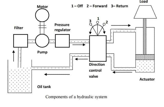
Hydraulic systems are power transmission assemblies that employ pressurized liquid as a fluid to transmit energy from a power generating source to an energy consuming point to perform useful work. The figure shows a simple circuit of a hydraulic system with basic components. Hydraulic systems are used for transmitting power through hydraulic oil. The hydraulic system works according to the principle of Pascal's law which states that “the pressure in a fluid at rest is transmitted uniformly in all directions”.
The fluid medium used is hydraulic oil, which can be mineral oil or water or combinations. This area is also known as hydraulic oil.
 hydraulic system components
Component functions
1. Hydraulic actuator
- It is a device used to convert fluid energy into mechanical energy to do useful work. The actuator may be of linear (e.g., hydraulic cylinder) or rotary (e.g., hydraulic motor) type to provide linear or rotary motion, respectively.
- Pressurized hydraulic fluid delivered by the hydraulic pump is supplied to actuators, which convert fluid energy into mechanical energy. This mechanical energy is used to do work.
-
TYPES OF ACTUATORS:
1. Linear Actuators (Hydraulic Cylinders)
2. Rotary Actuators (Hydraulic Motors)
The. Continuous Rotary Actuators
B. Semi-rotary actuators -
Actuator functions:
1) To produce movement in a line
2) To produce continuous rotary motion
3) To produce rotary or oscillatory motion less than 3600
4) Apply force and secure the work.
2. Hydraulic pump
- It is used to force fluid from the reservoir to the rest of the hydraulic circuit, converting mechanical energy into hydraulic energy.
- A pump that is the heart of a hydraulic system converts mechanical energy into hydraulic energy. Mechanical energy is delivered to the pump through a prime mover, such as an electric motor. Due to mechanical action, the pump creates a partial vacuum at its inlet. This allows atmospheric pressure to force the fluid through the inlet line and into the pump. The pump then pushes the fluid into the hydraulic system.
Importance of the pump:
1. They convert mechanical energy into hydraulic energy.
2. The volumetric efficiency of the pump is relatively high
3. They have high performance characteristics under different speed and pressure requirements
4.Pumps used to generate high pressure in the hydraulic system
3. Valves
- Valves are used to control the direction, pressure and flow rate of a fluid flowing through the circuit.
Engine 1 – Off 2 – Forward 3 – Return 3 2 1 Load Direction control valve Pump Oil tank Filter Actuator Pressure regulator. - A fluid power system can be divided into three segments. The power input segment consisting of the main motor and pump. The control segment consisting of valves that control direction, pressure, and flow. The power output segment, composed of the actuators and the load. This unit is dedicated to each of the following control valve categories.
1. Directional control valves
2. Pressure control valves
3. Flow Control Valves - DCVs control the direction of flow in a circuit, which among other things; can control the direction of the actuator. PCVs control the pressure level, which controls the output force of a cylinder or the output torque of an engine. FCVs control the flow rate of the fluid that controls the speed of the actuators.
Different types of valves and their functions:
4. External power supply (motor) is required to drive the pump.
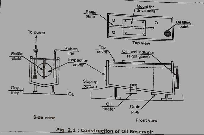
5. Oil tank or reservoir:
- This is an oil storage tank in which hydraulic oil is stored. The oil passes through several pipes and after carrying out useful work on the actuator; the oil returns to the oil tank. In low temperature regions, oil heaters are coupled to air tanks.
- The reservoir is used to hold hydraulic liquid, usually hydraulic oil.
6. Pipelines:
- Piping (Fluid Conduction Elements): It is the functional connection for oil flow in the hydraulic system. Oil flow efficiency is greatly influenced by the physical characteristics of piping systems.
- There are two tubes:
a) The tube that carries pressurized oil is called a pressure duct
b) Pipes that transport low pressure oil or used oil (called return pipes). - Hoses, tubes and pipe fittings are the parts of fluid power piping.
7. Filters
- It is used to remove any foreign particles, keeping the fluid system clean and efficient, as well as preventing damage to the actuator and valves.
- When hydraulic fluids are contaminated, hydraulic systems can become damaged and malfunction due to clogging and internal wear. They require filtration to remove contaminants.
- Filters are classified as
I. Reservoir filters:
ii. Line filters
iii. Offline filters
4. Other cleaning equipment -
Filter Functions:
1) Make sure the components are clean.
2) Reduce maintenance.
3) To remove siltation.
4) Increase system reliability.
5) Prevent solid contaminants from entering the system.
8. Pressure regulator
- Pressure regulator regulates (i.e. maintains) the required level of pressure in the hydraulic fluid.
- The piping shown in Fig. is of the closed loop type with fluid transferred from the storage tank to one side of the piston and returned from the other side of the piston to the tank. Fluid is removed from the tank by a pump that produces fluid flow at the required pressure level. If the fluid pressure exceeds the required level, the excess fluid returns to the reservoir and remains there until the pressure reaches the required level.
9. Accumulators
- Accumulators are devices that store hydraulic fluid under pressure. Storing hydraulic fluid under pressure is a way to store energy for later use. Perhaps the most common application for an accumulator is to supplement pump flow in a hydraulic system in which a high flow rate is required for a brief period of time.
-
Types of accumulators;
1. Accumulator loaded with weight
2. Spring accumulator
3. Accumulator charged with gas
4. Piston type
5. Bladder type
6. Type of diaphragm
10. Hydraulic power unit:
- The hydraulic power unit (supply unit) provides the energy required for the hydraulic installation.
- The main components of the power packs are – The reservoir (tank), Drive (electric motor), Hydraulic pump, Pressure relief valve, filter and cooler.
- The pump or motor unit can be mounted on the tank or separately, sets in horizontal or vertical configurations are usually available. The basic unit can be plumbed to the cylinders or actuators through a suitable control valve.
- Hydraulic units consist of a reservoir/tank that houses the hydraulic fluid, which is the working medium.
 Hydraulic power unit diagram
Hydraulic Power Pack Operation:
- The functioning of a power pack begins when the pump is started with the help of an electric motor attached to it. The oil is pumped from the reservoir along the suction line through a suction filter capable of retaining foreign particles up to 149
microns. - From the suction line, the oil is forced into the pressure line via the pump at 35 bars. There is provision to measure pressure with the help of a pressure gauge. An isolator is used to immediately measure pressure in any line.
- When the set pressure is reached, the fluid moves to the cylinder present in the device (clamp). The hydraulic energy of the fluid is converted back to mechanical energy by the cylinder.
- According to the energization direction of the solenoid valve, the linear movement of the clamps (tightening and loosening) is controlled. When the solenoid valve is energized in reverse, the part loosens. There is a return line provided so that the used fluid can be used again. Due to friction losses, the total energy is not converted into useful work, so some is converted into heat. Therefore, a heat exchanger is incorporated. The return line filter has a return capacity of 10 microns.
Cylinder movement is controlled by a three-position change in a control valve.
1. When the valve piston is changed to the upper position, the pipe pressure line is connected to port A and thus the load is raised.
2. When the valve position is changed to a lower position, the pipe pressure line is connected to port B and thus the load is reduced.
3. When the valve is in the center position, it blocks the fluid in the cylinder (keeping it in position) and closes the fluid line (causing all fluid leaving the pump to return to the tank through pressure relief).
Some questions related to the hydraulic circuit:
Draw a sketch of a simple oil hydraulic circuit and write down the name and working function of each of the components used in it.
Basic hydraulic circuit diagram:
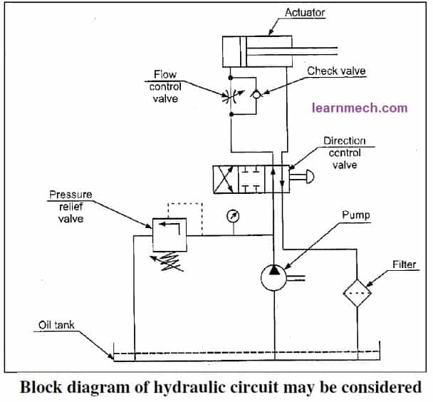 basic hydraulic circuit diagram
a) Oil Tank or Reservoir: This is an oil storage tank in which hydraulic oil is stored. The oil passes through several pipelines and after doing useful work in the actuator, the oil returns to the oil tank. In low temperature regions, oil heaters are connected to air tanks.
b) Filter: This element filters the oil before it goes to the next element, that is, the pump.
c) Pump: The hydraulic pump is the heart of any hydraulic system. Its main function is to create the flow of oil under pressure throughout the hydraulic system and therefore aid the transfer of power and movement (i.e. useful work).
d) Direction Control Valves/Flow Control Valves/Pressure Relief Valves (Fluid Control Elements): These valves are installed in the hydraulic system at specific locations. These valves control the flow of oil in the system. They also direct the flow of oil in the system, as well as controlling the actuator speed.
e) Actuators: (Elements for using Power Fluid): These elements are known as actuators (rotary or linear). Pressurized oil acts on the actuator elements. Oil gives or transfers its power to the actuator to create useful work or Mechanical Advantage.
f) Ducts (Fluid Conduction Elements): It is the functional connection for oil flow in the hydraulic system. Oil flow efficiency is greatly influenced by the physical characteristics of piping systems.
There are two tubes:
a) The tube that carries pressurized oil is called a pressure duct
b) Pipes that transport low pressure oil or used oil (they are called return pipes). Hoses, tubes, tube fittings are the parts of fluid power piping.