
CAD Tut 4.
Do this initial setup before starting any AutoCad drawing.
The following instructions will inform you on how to properly configure AutoCAD settings. This configuration is essential for you to produce a drawing that makes sense and is visually attractive. Read each step carefully before taking the required action.
1) Install and open AutoCAD (any version I'm using AutoCAD 2012)
2) Change the workspace view as per your need – Drafting and Annotation, Autocad Classic
3)
- Enable or manage toolbars. ADD or remove necessary toolbars. – Select the toolbars that you will use throughout the drawing. To do this, hover your mouse over an empty space at the top of the screen, next to the toolbars. Then right-click and select AutoCAD. A long list should appear, displaying several toolbars containing different commands. The most popular toolbars used for AutoCAD 2D drawings are the DRAW, MODIFY, and OBJECT PROPERTIES toolbars. Select these toolbars and they should appear on the screen.
- Check visual interference options like Ortho, Snap, Otrack
4) Go to model space. There are two views in AutoCAD: modelspace and paperspace. Your drawing must always be done in modelspace, and the dimensions that are added later must be represented in paperspace. To switch between modelspace and paperspace, view the tabs located at the bottom of the screen. One tab is labeled 'modelspace' and the other tabs are labeled 'sheet' or 'layout'. The 'sheet' or 'layout' tabs indicate paperspace. If you are in modelspace, the screen background should appear black. If you are in paperspace, the background should appear white.
Go to Format/Units/Next window will open, then check the units and change them.
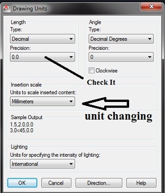 unit configuration
6) Set Boundaries: Boundaries indicate your drawing page. Your drawing must be in the Limits box because this will help in printing the same drawing;
Go to Format/Drawing Limits/
See Command Prompt
Specify the bottom left corner or (ON/OFF):
Specify the top right corner: 700,500 (for example)
To type.
Note- There is no change in sereen after limits command. The Zoom/All option of the Zoom command will zoom to the limits of the drawings.
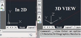
7) Check the coordinate system:
Cartesian or rectangular coordinate system
8) After finishing all this just type the command 're' or Z / All
Magnification- The Zoom command is used to view the drawing in enlarged or reduced view. Several options are
available in the Zoom command.
Command >> Zoom
Specify the window corner, enter a scale factor (nX or nXP), or
(All/Center/Dynamic/Extensions/Previous/Scale/Window/Object)
- All – Zoom /All, zooms in to the limits or the entire drawing, if the drawing exceeds the limits.
- Center – Zoom/Center expects the center point of the zoom and the zoom magnification.
- Dynamic – Enlarge the drawing with dynamic zoom according to the screen size. A dynamic window appears to specify the drawing area to be enlarged.
Or go to the View menu /Zoom/All
Tips:
The following lists the commonly used commands that are useful in creating an AutoCAD drawing:
- Cancel – cancels a command. 'ESC'
- Undo – undoes your last command. 'CTRL' + 'Z'
- Delete – deletes an object, line or other item. E' + 'ENTER' key
- Circle – creates a circle with a specific radius. 'C' key + 'ENTER' -> input radius length + 'ENTER' key
- Line – creates a line of a given length. 'L' key + 'ENTER' -> line input length + 'ENTER' key


