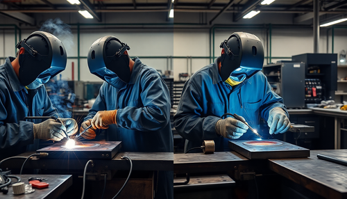
Sheet metal processing in traditional workshops generally involves processes such as shearing, punching and bending.
The punching process is known for its low or no cutting process and requires a significant number of dies. This results in high production costs, as hundreds of sets of molds may be required for a single product.
Using so many dies increases the cost of the product, resulting in excessive expenses.
To solve this problem and modernize sheet metal processing, laser processing technology was introduced. This reduced production costs and improved processing technology.
The implementation of laser cutting machines has greatly advanced sheet metal processing technology and revolutionized the way sheet metal is manufactured and processed.
Laser cutting technology and equipment are becoming increasingly popular and widely accepted among sheet metal processing companies. This is due to its numerous advantages, such as high processing efficiency, precision and good cutting quality, as well as the ability to perform three-dimensional cuts. As a result, laser cutting technology is gradually replacing traditional sheet metal cutting equipment such as CNC equipment, scissors, punches, flame cutting, plasma cutting and high pressure water cutting.
Laser cutting technology plays a crucial role in the development of sheet metal processing as it increases labor productivity and advances the field. With its high degree of flexibility, a laser cutting machine can significantly shorten the processing cycle, increase cutting speed and improve processing accuracy, contributing to faster product development. These benefits are attracting the attention of many manufacturing companies.
A laser cutter operates by emitting a laser beam that is focused by an optical path system into a high power density beam. The laser beam is directed to the surface of the part, causing it to reach its melting or boiling point. At the same time, a high-pressure gas stream blows away the molten or vaporized metal. As the laser beam moves across the workpiece, it cuts the material to form a slit.
The laser cutting process is a modern and advanced metal cutting method that uses an invisible laser beam instead of a traditional mechanical knife. This process is characterized by its high precision, fast cutting speed and ability to automatically nest cuts to conserve material. The laser cutting process also results in a smooth cut and lower processing costs, making it a more efficient alternative to traditional metal cutting methods.
One of the main benefits of the laser cutting process is that the mechanical part of the laser cutter never comes into contact with the part, eliminating the risk of scratches or other surface damage. The laser cutting process is also fast and produces a smooth, even cut, which often eliminates the need for additional processing. The heat-affected zone is small, leading to minimal plate deformation and narrow cuts (0.1 to 0.3 mm), and the incision is free from mechanical stresses and shear burrs.
Laser cutting is also highly repeatable without damaging the surface of the material. It can be easily programmed with CNC software to process any design, making it an economical option for cutting large format sheets without the need for molds. Carbon steel plates up to 12mm thick and stainless steel plates up to 10mm thick are typically recommended for laser cutting.
In addition to high precision, the laser cutting process is also highly adaptable, as it does not exert cutting force and does not generate tool wear. This makes it suitable for cutting a wide variety of materials, including simple or complex parts. With automatic nesting capabilities, laser cutting also offers economic benefits by optimizing material utilization.
Types of laser cutting machine
The current laser cutting machine market is broadly divided into three types based on the type of laser generator used: CO2 laser cutting machine, YAG (solid state) laser cutting machine, and fiber laser cutting machine .
CO2 Laser Cutting Machine
CO 2 laser cutting machines are capable of cutting carbon steel up to 20mm thick, stainless steel up to 10mm thick and aluminum alloy up to 8mm thick. The wavelength of the CO2 laser is 10.6μm, which is easily absorbed by non-metallic materials such as wood, acrylic, PP and plexiglass, allowing high-quality cutting of these materials. However, the photoelectric conversion rate of CO 2 lasers is relatively low, around 10%.
To increase cutting speed and ensure smooth cuts, CO2 laser cutting machines are equipped with a nozzle that blows oxygen, compressed air or N2 inert gas into the beam output. To improve the stability and service life of the power supply, the CO2 gas laser must approach the discharge stability of high-power lasers.
According to international safety standards, laser danger levels are divided into 4 levels, with CO 2 lasers falling into the least dangerous category.
Related reading: Laser Product Safety Levels
The main advantage of CO2 laser cutting machines is their high power, with a general power range of 2000 to 4000W. This allows you to quickly cut full-size stainless steel and carbon steel up to 25mm thick, aluminum up to 4mm thick, acrylic plates up to 60mm thick, wooden plates, PVC plates and cutting sheets, among others.
Another advantage of CO2 lasers is that they emit a continuous laser beam, which results in the smoothest cutting cross-section among the three types of laser cutting machines.
Main market focus: Cutting medium and heavy sheets with thicknesses ranging from 6 to 25mm, serving mainly large and medium-sized companies and some purely foreign laser cutting companies.
However, due to factors such as high laser maintenance costs and high main engine power consumption, the market has declined significantly in recent years due to the huge impact of fiber laser cutting machines.
YAG Laser Cutting Machine (Solid State)
YAG solid state laser cutting machine is known for its low cost and stability, but its energy efficiency is typically less than 3%. Most of its products have an output power of less than 800W, which limits its use mainly to punching, spot welding and thin plate cutting.
Its green laser beam can be used in pulsed and continuous wave modes, with short wavelength and good condensation properties. This makes it suitable for precise machining, especially in the case of pulsed hole processing, but also for cutting, welding and lithography.
However, the YAG solid-state laser has a wavelength that is not easily absorbed by non-metallic materials, making it unsuitable for cutting non-metallic materials. Improving the stability and longevity of your power is crucial to your development.
To achieve this, it is necessary to use a large-capacity, long-life optical pump excitation light source. Using semiconductor optical pumps can significantly increase your energy efficiency.
The main advantages: This machine has the ability to cut aluminum, copper and most non-ferrous metal materials, which other laser cutting machines cannot cut.
In terms of cost and maintenance, the machine is relatively inexpensive to purchase and requires simple maintenance. Many of the main technologies were successfully developed by national companies.
Furthermore, the cost of accessories and maintenance is low, making the machine easier to operate and maintain, even for those with limited technical knowledge.
Main focus on the market: Cutting materials with a thickness of 8 mm or less.
This machine is mainly used by small businesses for their own use, as well as medium-sized businesses and most users in industries such as sheet metal manufacturing, home appliance manufacturing, kitchenware manufacturing, decoration, advertising and others with low demands of processing. .
In the future, it may gradually replace traditional processing equipment such as wire cutting, CNC punching, water cutting and low-power plasma.
Optical Fiber Laser Cutting Machine
Optical fiber laser cutting machine offers highly flexible laser transmission through optical fibers resulting in fewer failure points, easy maintenance and high speed, making it highly advantageous for cutting thin plates within 4mm. However, its quality in cutting thick plates is inferior due to the influence of solid laser wavelengths.
The wavelength of the optical fiber laser cutting machine is 1.06μm, which is not easily absorbed by non-metallic materials, making it unsuitable for cutting non-metallic materials. Its photoelectric conversion rate reaches 25%.
In terms of electricity consumption and cooling system parameters, the fiber optic laser has clear advantages. However, due to its short wavelength, it poses the greatest danger to the eyes according to international safety standards and as a result, fiber optic laser processing must be carried out in a completely enclosed environment for safety reasons. .
Despite being an emerging laser technology, the optical fiber laser cutting machine is not as widely used as the CO laser cutting machine. 2 laser cutting machine.
The main advantages: The fiber laser cutting machine has a high photoelectric conversion rate, low power consumption and the ability to cut stainless steel plates up to 12mm as well as carbon steel plates. It is the laser cutting machine with the fastest cutting speed among the three machines.
Furthermore, it is suitable for fine cutting due to its fine cutting and good stitch quality.
Main market focus: Cutting materials with a thickness of 12 mm or less, mainly in high-precision processing of thin sheets.
This machine is designed for manufacturers with extremely high processing accuracy and efficiency requirements.
It is predicted that with the advent of lasers with output powers of 5,000 W or more, fiber laser cutting machines will eventually replace most of the market with high-power CO2 laser cutting machines.
Laser cutting method
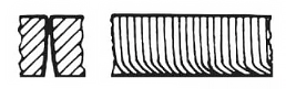
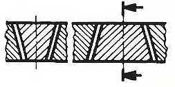
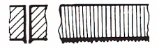
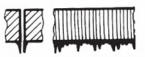
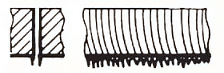
Figure 1 shows the three laser cutting methods.
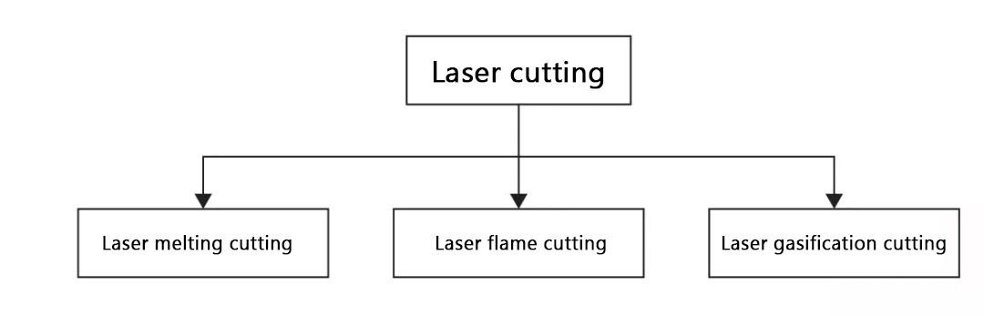
Figure 1: Laser cutting method
Laser Melting Cutting
(1) In laser fusion cutting, a high-purity inert cutting gas is used in conjunction with a laser beam to partially melt the workpiece. The molten material is then expelled by a stream of air. This process is called laser fusion cutting because the material transfer occurs only in the liquid state.
(2) The cutting gas moves the molten material away from the crack, but does not actively participate in the cutting process.
(3) Compared to vaporization cutting, laser fusion cutting allows for higher cutting speeds because the energy required to melt the material is generally less than the energy required to vaporize it. The laser beam is only partially absorbed during the process.
(4) The maximum cutting speed is influenced by several factors, including laser power, plate thickness, material melting temperature, air pressure at the cutting edge, and material thermal conductivity. At a given laser power, these factors determine the limiting conditions.
(5) Laser fusion cutting produces oxidation-free cuts for ferrous materials and titanium, and a laser power density of 104 W/cm 2 to 105 W/cm 2 for steel materials. This power density melts the material without causing it to vaporize.
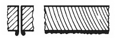
Laser flame cutting
Laser flame cutting is different from laser fusion cutting because it uses oxygen as the cutting gas, leading to a chemical reaction between the oxygen and the heated metal, which heats the material further. This method results in a higher cutting rate for the same thickness of structural steel compared to fusion cutting.
However, the cut quality is not as good as that produced by fusion cutting, as wider cuts, significant roughness, a larger heat affected zone, and poor quality edges are produced.
(1) When working with precision models and sharp edges, laser cutting may not be the best option as there is a risk of burning the sharp edges. To minimize the heat-affected zone, pulsed mode lasers can be used.
(2) The cutting speed is determined by the laser power used. The limiting factors for a given laser power are the availability of oxygen and the thermal conductivity of the material.
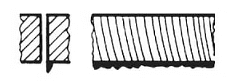
Laser v aporization c revealing
Laser vaporization cutting involves vaporizing the material at the cutting edge, which requires high laser power. To prevent material vapor from condensing on the slit wall, the thickness of the material must not significantly exceed the diameter of the laser beam. This process is only suitable for the limited use of iron-based alloys and cannot be used on materials such as wood and ceramics, which typically result in thicker cuts.
(1) Optimal beam focus in laser vaporization cutting depends on factors such as material thickness and beam quality.
(2) The ideal focus position is affected by laser power and heat of vaporization.
(3) For certain sheet thicknesses, the maximum cutting speed is inversely proportional to the vaporization temperature of the material.
(4) The required laser power density may be greater than 108 W/cm2 depending on the material, cutting depth and beam focus position.
(5) For a given sheet thickness, the maximum cutting speed is limited by the speed of the gas jet, assuming sufficient laser power.
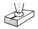
Laser cutting process
The process refers to the interaction between a laser beam, a process gas and the part to be treated.
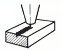
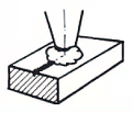
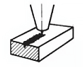
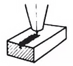
Figure 2 shows the processing parameters.
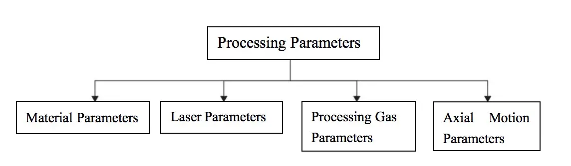
Fig.2 Processing parameters
Cutting process
Before cutting, the laser heats the part to the temperature necessary to melt and vaporize the material. The cutting plane consists of a nearly vertical plane that absorbs laser radiation to heat and melt the material.
In laser flame cutting, a flow of oxygen is introduced into the slit, further heating the fusion zone to a temperature close to boiling. The resulting vaporization removes the material, while the liquefied material is expelled from the bottom of the part with the help of the heated gas.
In laser fusion cutting, the liquefied material is expelled with the gas, which protects the gap from oxidation. The continuous fusion zone gradually moves in the direction of the shear, creating a continuous crack.
Many important aspects of the laser cutting process occur in this zone, and analysis of these activities provides important information about laser cutting. This information allows the calculation of cutting speed and helps explain the formation of design line characteristics.
Material properties
Cutting results on the workpiece can vary, from a clean cut to rough edges or excessive burning. Cut quality is influenced by several factors, including:
(1) Alloy composition: The composition of the alloy affects its strength, specific gravity, weldability, oxidation resistance and acidity to a certain extent. Some of the important elements in ferrous alloy materials are carbon, chromium, nickel, magnesium and zinc. The higher the carbon content, the more difficult it is to cut the material (the critical value is considered to be a carbon content of 0.8%). Carbon steels such as St 37-2, StW 22 and DIN 1.203 can be cut well with lasers.
(2) Microstructure of the material: In general, the finer the particles that make up the material, the better the cutting quality.
(3) Surface quality and roughness: If the surface has areas of rust or oxidation, the cutting profile will be irregular and will have many breakage points. To cut corrugated cardboard, select the maximum thickness cutting parameter.
(4) Surface treatment: The most common surface treatments are galvanizing, painting, anodizing or covering with plastic film. Zinc-treated sheets tend to have slow edges. The quality of the cut depends on the composition of the painted product. Boards covered with plastic film are very suitable for laser cutting. The layered edge must always be on top of the cutting part for trouble-free capacitive sensing and optimal adhesion of the coated layer.
(5) Beam reflection: The way the light beam is reflected from the surface of the part depends on the base material, surface roughness and treatment mode. Some aluminum, copper, brass and stainless steel alloys have high reflectivity characteristics. Particular care must be taken when adjusting the focus position when cutting these materials.
(6) Thermal conductivity: Materials with low thermal conductivity require less energy than materials with high thermal conductivity during welding. For example, chromium-nickel alloy steel requires less energy than structural steel and less heat is absorbed during processing. Materials such as copper, aluminum and brass conduct heat away from the target point of the beam, making it more difficult to melt the material in the heat-affected zone.
(7) Heat-affected zone: Laser flame cutting and laser fusion cutting cause material variation in the edge area of the cut material. The range of the heat-affected zone is related to the thickness of the base material.
Table 1 lists some reference values.
Table 1 Relationship between material thickness and heat-affected zone
| Material thickness/mm | Heat Affected Zone/mm | ||
|---|---|---|---|
| Saint 37 | Carbon steel | Aluminum | |
| 1 | 0.05 | 0.05 | 0.10 |
| two | 0.10 | 0.10 | 0.20 |
| 3 | 0.15 | 0.15 | 0:30 |
| 4 | 0.20 | 0.35 | 0.40 |
| 5 | 0.25 | 0.34 | 0.50 |
| 6 | 0:30 | 0.55 | 0.60 |
| 8 | 0.40 | 0.75 | 0.70 |
| 10 | 0.50 | 0.85 | —— |
| 12 | 0.60 | —— | —— |
The table shows that:
(1) When processing low-carbon steel or oxygen-free steel, the quenching effect in the heat-affected zone is reduced.
(2) High carbon steel such as Ck60 will harden the edge area.
(3) The heat-affected zone of a rolled aluminum alloy will be slightly softer than the rest of the material.
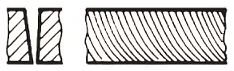
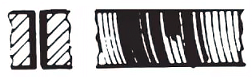
Laser Cutting Incision Assessment Analysis
Processability of different materials
(1) Structural steel
Oxygen cutting can be used, however, the cutting edge may be slightly oxidized.
For sheets with a thickness of 4 mm, nitrogen gas is suitable for high pressure cutting.
When handling complex contours and small holes (with a diameter smaller than the thickness of the material), pulse mode should be used to avoid cutting sharp corners.
Structural steel: cutting with O 2
| Defect | Possible cause | Solution |
No burrs, consistent line of pull
|
Right power Proper feeding rate |
|
The pull line at the bottom is quite offset and the cut at the bottom is wider
|
Feed rate is too high Laser power is too low Air pressure is too low Focus is too high |
Reduce the feed rate Increase laser power Increase air pressure Less focus |
The burrs on the bottom surface are slag-like, drip-shaped and easy to remove

|
Feed rate is too high Air pressure is too low Focus is too high |
Reduce the feed rate Increase air pressure Less focus |
Metal burrs connected together can be removed as a whole piece
|
Focus is too high | Less focus |
Metal burrs on the bottom surface are difficult to remove

|
Feed rate is too high Air pressure is too low impure gas Focus is too high |
Reduce the feed rate Increase air pressure Use purer gas Less focus |
Only one side has burrs
|
Incorrect nozzle alignment Defective nozzle |
Centering nozzle Change nozzle |
When cutting structural steel, the following must be considered:
- The higher the carbon content, the more prone the cutting edges are to quenching and excessive corner burning.
- Sheets with higher alloy content are more difficult to cut compared to those with lower alloy content.
- A surface that has been oxidized or sandblasted will result in poor cut quality.
- Residual heat on the surface of the plate can negatively impact the cutting result.
- For sheets thicker than 10 mm, better results can be achieved by using special laser electrodes and lubricating the surface of the part during the process.
- To relieve tension, it is recommended to cut steel sheets only after secondary treatment.
- To obtain a clean surface on structural steel, the following guidelines must be followed:
Si ≤ 0.04%: laser processing is preferred.
Si < 0.25%: in some cases poor cutting quality may occur.
Si > 0.25%: not suitable for laser cutting.
| Defect | Possible cause | Solution |
Material is discharged from above
|
Power is too low Feed rate is too high |
Increase power Reduce the feed rate |
Sloped surface cuts well on both sides, but poor on both sides
|
The polarizing mirror is not suitable, the installation is incorrect or defective The polarizing mirror is installed in the position of the deflection mirror | Check the polarizing mirror Check the deflection mirror |
Blue plasma, the workpiece is not cut
|
Process gas error (N2) Feed rate is too high Power is too low |
Use oxygen as processing gas Reduce the feed rate Increase power |
The cutting surface is not precise

|
Air pressure is too high The nozzle is damaged Nozzle diameter is too large Bad material |
Reduce air pressure Replace the nozzle Install the right nozzle Use a smooth surface Homogeneous material |
No burrs, the inclined incision of the pull line becomes narrower at the bottom
|
Feed rate is too high | Reduce the feed rate |
Crater

|
Air pressure is too high Feed rate is too low Focus is too high Rust on the leaf surface Overheated part impure material |
Reduce air pressure Increase feeding rate Less focus Use better quality material |
Very rough cutting surface
|
Focus is too high Air pressure is too high Feed rate is too low The material is very hot |
Less focus Reduce air pressure Increase feeding rate Cooling material |
Several key parameters that affect the process
N1 gas parameters
- Gas type: nitrogen, oxygen and compressed air
- Gas purity: Generally between 99.99% and 99.999% of air pressure.
- The maximum air pressure during low pressure cutting is 5 bar, and the maximum air pressure during high pressure cutting is 20 bar between the nozzle and the plate;
- The distance between the nozzle opening and the surface of the part must be as small as possible.
- The shorter the distance, the greater the actual airflow through the incision.
- The clearance is generally between 0.5 and 1.5 mm.
( 2 ) Stainless steel
- Oxygen cutting is used when there is minimal oxidation of the edge.
- By combining high power and high pressure nitrogen, a cutting speed equivalent to or faster than oxygen cutting can be achieved.
- When using nitrogen to process stainless steel thicker than 4 mm, it is necessary to reset the focus position and decrease the speed to minimize burr formation.
- For sheets thicker than 5 mm, oxygen cutting is suitable; however, it is necessary to decrease the feed speed and employ laser pulse mode.
- The same nozzle height should be used for drilling and cutting. For cutting stainless steel, the recommended method is high pressure nitrogen.
| Defect | Possible cause | Solution |
Produces small, regular burrs
|
Focus is too low Feed rate is too high |
Increase focus Reduce the feed rate |
Long and irregular filament-like burrs are produced on both sides and the surface of the large plate becomes discolored
|
Feed rate is too low Focus is too high Air pressure is too low The material is very hot |
Increase feeding rate Less focus Increase air pressure Cooling material |
Only produce long, irregular burrs on one side of the cutting edge

|
The nozzle is not centered Focus is too high Air pressure is too low The speed is very low |
Centering nozzle Less focus Increase air pressure Speed up |
| Yellow cutting edges | Nitrogen contains oxygen impurities | Use good quality nitrogen |
Plasma is generated in a straight section
|
Feed rate is too high Power is too low Focus is too low |
Reduce the feed rate Increase power Increase focus |
| Beam Divergence | Feed rate is too high Power is too low Focus is too low |
Reduce the feed rate Increase power Increase focus |
| Plasma on the corner | Angle tolerance is very high Very high modulation Very high acceleration |
Reduce angular tolerance Reduce modulation or acceleration |
| The beam diverges at the beginning | Very high acceleration Focus is too low Molten material has not been discharged |
Decrease acceleration Increase focus Drilled hole |
| Sharp cut | The nozzle is damaged The lens is dirty |
Replace the nozzle to clean the lens, replace if necessary |
Material is discharged from above
|
Power is too low The feed rate is too large Air pressure is too high |
Increase power Reduce the feed rate Reduce air pressure |
( 3 ) Aluminum
Aluminum and its alloys are best suited for continuous cutting.
N2 laser power
There is a choice between continuous or pulsed mode, with continuous mode typically used for quick, routine cutting operations.
Pulsed mode is employed for high-precision cutting operations that have stringent requirements for the end face and operates significantly slower than continuous mode.
- When cutting with oxygen, the cutting surface is rough and hard, resulting in a small flame that is difficult to eliminate.
- When cutting with nitrogen gas, the cutting surface is smooth. Furthermore, when processing boards smaller than 3 mm, optimal adjustments can result in virtually burr-free incisions. However, for thicker sheets, burrs that are difficult to remove may occur.
- Pure aluminum is difficult to cut due to its high purity.
- The higher the alloy content, the easier the material will be to cut.
Note: Before cutting aluminum, a “reflective absorption” device must be installed in the system, otherwise the optical components will be damaged.
Aluminum alloy: cutting with N 2 high pressure
| Defect | Possible cause | Solution |
Both sides have long irregular filamentous burrs, which are difficult to remove
|
Focus is too high Air pressure is too low Feed rate is too low |
Less focus Increase air pressure Increase feeding rate |
| Long, irregular burrs on both sides Can be removed manually 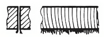
|
Feed rate is too low | Increase feeding rate |
| Sharp cut | Nozzle diameter is too large The nozzle is damaged Air pressure is too high |
Install the right nozzle Replace the nozzle Reduce air pressure |
Produces fine, even burrs that are difficult to remove

|
Focus is too low Feed rate is too high |
Increase focus Reduce the feed rate |
| Plasma is generated in a straight section | Feed rate is too high Focus is too low |
Reduce the feed rate Increase focus |
| Beam Divergence | Feed rate is too high | Reduce the feed rate |
| Plasma on the corner | Angle tolerance is very high Very high modulation Very high acceleration |
Reduce angular tolerance Reduce modulation or acceleration |
| The beam diverges at the beginning | Approach speed is too high Focus is too low |
Reduce approach speed Increase focus |
| Sharp cut | The nozzle is damaged | Replace the nozzle |
Material is discharged from above
|
Power is too low The feed rate is too large |
Increase power Reduce the feed rate |
( 4 ) Titanium
Titanium plates are cut using argon and nitrogen as process gases. Other parameters can be found in nickel-chromium steel.
( 5 ) Copper and brass
- Both copper and brass have high reflectivity and excellent thermal conductivity.
- Brass up to 1 mm thick can be cut with nitrogen gas.
- For processing copper with a thickness of less than 2 mm, oxygen gas must be used.
Note: Cutting copper and brass is only possible if a “reflection absorption” device is installed in the system, otherwise the optical components will be damaged.
( 6 ) Synthetic materials
C output speed
The cutting speed of a sheet depends on its thickness, with thinner sheets allowing faster cutting.
When straight contours are being processed, the cutting speed may reach its maximum set value.
However, when processing arc contours or corners, the cutting speed will be automatically reduced to ensure high-quality processing.
Laser power is also a factor in processing speed, with higher laser power resulting in faster processing.
It is important to consider the potential risks of cutting synthetic materials and the emission of harmful substances when using a laser cutter.
Synthetic materials that can be processed include thermoplastics, thermosetting materials and artificial rubber.
However, it is not recommended to use a laser cutter to process PVC or polyethylene due to the toxic gases they release. Water cutting is a safer alternative for these two materials.
Acrylic glass can be cut with a laser and nitrogen is used as the processing gas. Pressure must be kept below 0.5 bar to obtain a smooth cutting surface.
( 7 ) Organic
Acrylic glass can be cut using a laser with nitrogen as the processing gas. To obtain a smooth cutting surface, the air pressure must be less than 0.5 bar.
There is a fire risk associated with cutting organic materials, whether using nitrogen or compressed air as the processing gas.
Materials such as wood, leather, cardboard and paper can be laser cut, resulting in burnt (brown) edges. The faster the feed rate, the less carbonization.
When cutting plywood, clean cuts cannot be guaranteed due to the variable composition of each glue layer.