In recent years, we have seen an increasing prominence of laser cutting machines in the growth of the sheet metal industry. The cutting process involves six practical functions that, when used, can significantly increase the processing efficiency and cutting performance of the laser cutting machine.
1. Jump
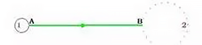
Leapfrog is a term used in laser cutting to describe the movement of the cutting head between cuts. In this process, after cutting hole 1, the cutting head moves from point A to point B to cut hole 2. During this movement, the laser is turned off and the machine runs without actually cutting, which is known as idle running. .
Early laser cutters had a specific idle operation process, as illustrated below. The cutting head performed three sequential actions during idling: it rose to a safe height, leveled off to reach above point B, and then lowered.
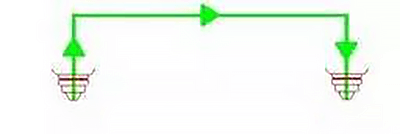
Reducing idle time can increase machine efficiency. To achieve this, the three idling actions (up, level and down) can be performed simultaneously. During the movement from point A to point B, the cutting head moves up and approaches point B and at the same time goes down. This simultaneous execution of actions reduces idle time, as shown in the figure below.

The idle movement of the cutting head is similar to an arc drawn by a jumping frog. This is considered a notable technical advance in the development of laser cutting machines. The frog's jumping action only takes the time of the plane movement from point A to point B, eliminating the time of rising and falling. Just like a frog jumps to capture its food, the “capture” function for the frog's jumping function in laser cutting machines is of high efficiency. Currently, laser cutting machines without the frog jumping function are no longer considered conventional.
two. Auto-focus
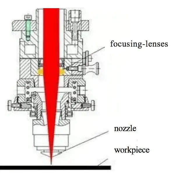
When cutting various materials, it is crucial that the focus of the laser beam falls on different sections of the workpiece's cross-section. To achieve this, the position of the focal point must be adjusted, which is known as focus adjustment.
Previously, laser cutting machines were mainly manually focused. However, today, many manufacturers offer machines with autofocus.
Some people may think that adjusting the height of the cutting head is enough to change the focus position. However, this is not the case. The distance between the nozzle and the workpiece (nozzle height) remains constant at around 0.5 to 1.5 mm during the cutting process, which means that the cutting head cannot be raised or lowered to adjust the focus .
Additionally, the focal length of the focusing lens cannot be changed, so it cannot be used to adjust focus. The only way to change the focus position is to change the position of the focus lens. If the focusing lens is lowered, the focusing position will also be lowered and vice versa. This focus adjustment method is accomplished by using a motor to move the focusing lens up and down, enabling autofocus.
Another way to achieve autofocus is to use a variable curvature reflector or adjustable lens placed before the beam enters the focusing lens. By changing the curvature of the reflector, the angle of divergence of the reflected beam is changed, thus changing the position of the focus, as illustrated in the figure.
With the auto-focus function, the efficiency of laser cutting machines can be significantly improved. Processing time for thick plates can be greatly reduced as the machine can quickly and automatically adjust the focus to the most suitable position for parts of different materials and thicknesses. This results in greater productivity and more precise cuts.
3. Automatic edge finding
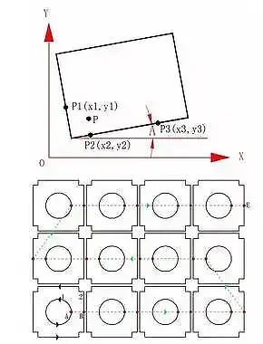
As shown in the illustration, when a sheet is placed on a table, if it is tilted, it may result in waste during the cutting process. However, if the tilt angle and origin of the sheet can be detected, the cutting process can be adjusted to match the angle and position of the sheet, thereby reducing waste.
To solve this, a feature called “automatic edge finding” was developed. When activated, the cutting head starts at point P and automatically detects three points on the two vertical sides of the sheet, P1, P2 and P3, and then calculates the draft angle (A) and the origin of the sheet.
Thanks to this function, the efficiency of the machine is improved, as it eliminates the need for manual adjustment of the part, which is a time-consuming task, especially considering the weight of the part (hundreds of kilograms).
A high-power laser cutting machine is a complex system that combines light, machinery and electricity, and often has subtle complexities. Let's take a closer look at these subtle aspects.
4. Concentrated drilling
Concentrated drilling, also known as pre-drilling, is a process separate from machine functions.
When cutting thicker sheets with a laser, each contour of the cutting process goes through two stages: drilling and cutting.
Conventional process (point A drilling → cutting profile 1 → point B drilling → cutting profile 2 →…).
Centralized drilling involves performing the drilling process across the entire steel sheet in a centralized manner before proceeding with the cutting process.
Concentrated drilling process (complete drilling of all contours → return to starting point → cut all contours).
The total machine path length is greater when using concentrated drilling compared to traditional machining methods.
So why is centered piercing used? One of the reasons is to avoid overheating.
During the process of drilling into a thick plate, heat builds up around the drilling point. If cutting is carried out immediately after drilling, overheating may occur.
With the centralized drilling process, the heat has enough time to dissipate before cutting is performed again after all drilling is complete. This helps to avoid the overheating phenomenon.
Centralized drilling can increase processing efficiency. Currently, there are still many laser cutting machines that do not have automatic focusing.
When cutting thick plates, the process parameters (such as laser mode, power, nozzle height, auxiliary gas pressure, etc.) are different during the drilling and cutting steps. The nozzle height is greater when drilling than when cutting.
With traditional processes (e.g. drilling profile 1, then cutting profile 1, then drilling profile 2, then cutting profile 2, and so on), the focus of the laser beam must be manually adjusted to the ideal position. cutting, in order to guarantee quality and efficiency. This manual adjustment can be a nightmare because the focus must be changed from the drilling position to the cutting position several times throughout the process. As a result, drilling time is longer because the focus is not in the ideal position.
However, with centered drilling, the focus can first be adjusted to a suitable drilling position. After drilling is complete, the machine can be paused and the focus position can be changed to the ideal cutting position. This can reduce drilling time by more than half, significantly improving efficiency. If necessary, other process parameters can be adjusted or changed between centralized drilling and cutting (e.g., air and continuous wave can be used for drilling, while oxygen can be used for cutting, with enough time to complete the gas exchange between them).
The focusing lens is often called the F-axis. It is possible to call it the H-axis “zoom” (Hand) if manual zoom is used for centered drilling and cropping.
Centralized piercing also presents risks. If there is a collision during cutting that causes the sheet to shift, the uncut portion may be wasted. This process requires the support of an automatic programming system.
5. M micro-connection
During the laser cutting process, the sheet is held in place by a serrated support bar. If the cut pieces are too small, they may not fit through the opening in the support bar. If they are too large to be supported by the support bars, they may become unbalanced and warp. This could result in a high-speed cutting head collision, causing stalling or damage to the cutting head.
This problem can be solved through the “bridge cutting (microjoint) process”. When programming laser cutting into graphics, the closed contour is intentionally broken in several places so that after cutting the parts remain attached to the surrounding material without falling out. These breaks are known as “bridge locations.”
This process is also known as “breakpoints” or “microjoins” (a term derived from a literal translation of MicroJoint). The rupture distance, which is around 0.2 to 1mm, is inversely proportional to the thickness of the sheet.
Different terminologies are used based on different perspectives:
- Based on the outline, if it is broken, it is called a “breakpoint”.
- Depending on the part, if it adheres to the base material, it is called “bridging” or “microconnection”.
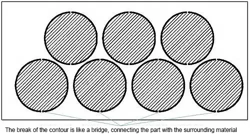
Bridges connect the part to the surrounding material and advanced programming software automatically adds the appropriate number of bridges based on the profile length.
You can differentiate between inner and outer contours and determine whether to add bridge locations. Inner contours (scrap) without bridging locations will fall out, while outer contours (parts) with bridging locations will remain attached to the base material and will not fall out, eliminating the need for sorting.
6. Common Edge Trimming
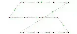
If the contours of adjacent pieces have straight edges and the same angle, they can be combined into a single straight line and cut only once. This is known as “common edge cutting”.
Common edge cutting reduces cutting length and significantly improves process efficiency. It does not require the pieces to be rectangular in shape, as shown in the illustration below.
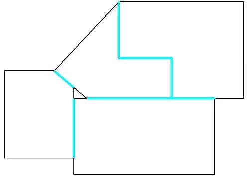
The blue lines in the illustration are common edges.
Ordinary edge cutting not only saves time during the cutting process, but also decreases the number of perforations. The benefits are evident.
For example, if common edge cutting saves 1.5 hours per day, that equates to approximately 500 hours per year. At a combined cost of $100 per hour, this would equate to an additional $50,000 per year.
Cutting common edges requires the use of intelligent automatic programming software.