Although there are no technical secrets in the welding process, there are several welding technologies, methods and processes that can facilitate the welding process. These processes are called technical know-how.
Welding knowledge can save time, cost and labor and can even determine the success or failure of welding as well as profits and losses. Most welding processes are based on scientific research, while some rely on actual welding experience.
This article aims to present a practical synthesis of welding experience.
1 . Welding process problems and solutions
1.1 C elding of thick plate and thin plate
1.1.1 When welding steel parts with GMAW and FCAW, if the thickness of the part exceeds the welder's maximum welding current, how to deal with it?
To prevent cracking of the weld or incomplete fusion, the metal must be preheated before welding. The welding area of the part can be preheated using propane, standard gas, or an acetylene torch. The recommended preheating temperature range is 150-260℃, after which the welding process can be started. The main purpose of preheating the metal in the welding area is to prevent rapid cooling, which can cause problems in the welding area.
1.1.2 If it is necessary to weld a thin metal covering on a thick steel pipe by GMAW or FCAW, if the welding current cannot be adjusted correctly, two situations may occur:
- First, to prevent the thin metal from burning and reduce the welding current, the thin metal cover cannot be welded to the thick steel pipe at this time;
- Secondly, the welding current will burn through the thin metal covering.
How to deal with this?
There are two main solutions.
① Adjust the welding current to avoid burning the thin metal cover. Furthermore, preheat the thick steel pipe using a welding torch and then weld the two metal structures together using the thin plate welding process.
② Adjust the welding current to suit the welding of thick steel pipe. During welding, keep the residence time of the welding arc on the thick steel pipe at 90% and reduce the residence time on the thin metal cover. It is important to note that only by mastering this technique will you be able to obtain good welded joints.
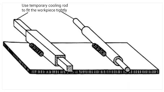
1.1.3 When a thin-walled tube or a thin-walled rectangular tube is welded to a thick plate, the electrode is easy to burn through the thin-walled tube. Besides the two solutions above, is there any other solution?
In welding processes, a cooling rod is often used to prevent burns. When a solid round bar is inserted into a thin-walled tube or a solid rectangular bar is inserted into a rectangular tube, heat is absorbed by the solid bar and prevents the thin-walled part from burning.
Typically, a solid round or rectangular bar is firmly installed in most hollow or rectangular pipe materials. When soldering, it is important to keep the solder away from the end of the pipe, as this area is the most vulnerable to burns.
Figure 1 shows a schematic diagram of how an integrated cooling rod can be used to prevent burns.

Figure 1. Use the built-in cooling rod to avoid burning
1.1.4 When it is necessary to weld a galvanized or chromium-containing material to another part, what should be done?
Best practice is to sand or sand the area around the weld before welding. This is because galvanized or chromium-containing metal sheets can pollute and weaken the weld, as well as releasing toxic gases during welding.
1.2 Vessel roofing and frame structure
1.2.1 If a welding process (such as brazing) is used to seal a buoy or the end of a hollow structure, what will be done to prevent hot air from entering the vessel and causing the vessel to rupture during final sealing of the vessel ? weld?
③ Firstly, a pressure relief hole with a diameter of 1.5mm is drilled in the pontoon to facilitate the circulation of hot air and external air near the weld. Then, sealing welding is carried out, and finally the pressure relief hole is sealed by welding.
Figure 2 shows the schematic diagram of a sealed welding pontoon or closed vessel.

Fig.2 Schematic diagram of a narrow welding pontoon or closed vessel
During welding of the gas storage container structure, the pressure reducing hole can be used. However, it is essential to note that welding in a closed container is highly dangerous. Before welding, it is essential to clean the inside of the container or pipe and avoid any flammable or explosive materials or gases.
When it comes to welding mesh, wire mesh or extended metal to the steel structure via GMAW, FCAW or TIG, the wire mesh is prone to burning and the weld may not fuse properly during the process. To deal with this problem, non-metallic washers must be placed on the wire mesh or extension metal, and the washer, wire mesh and frame must be fixed together.
It is important to note that chrome-containing or galvanized washers are not permitted, and the washer must be uncoated as illustrated in Fig. 3 (a).

Figure 3. Sketch of welding of wire mesh and frame structure
② To serve as a heat sink, a larger washer is positioned on top of the washer at the welding location.
The top washer must have a larger hole than the bottom washer to prevent them from being welded together.
Subsequently, the plug is welded through the two holes in the joint, ensuring that the weld remains at the bottom of the joint.
The operator may use alternative heating methods, being cautious to prevent the surrounding grille or wire mesh from burning, as illustrated in Figures 3(b) and (c).
③ Another technique involves using a metal strip with a hole, aligning it with the welding position, placing the heat sink washer and then performing plug welding, as shown in Figure 3 (d).
Related Reading: Wire Mesh Weight Calculator
1.3 R repair of welded components
1.3.1 In addition to the commonly used bolt opener, what other methods can be used to remove damaged or rusted bolts?
Two methods are introduced here :
① If the installed bolt is not damaged during heating, the nut and nut assembly can be heated using an oxygen-acetylene torch until glowing. Then quickly quench with water to make screw removal easier. This process may require several heating and cold quenching cycles.
② If the screw, nut or honeycomb groove is damaged or lost, place a nut on the top or remaining part of the screw head, tighten the nut, and then fill the metal inside the nut and screw it using any welding method. This method will connect the nut and remaining portion of the bolt, providing a new attachment point. Heat can also be used to tighten the screw.
The residual part of the fixed screw can be removed by welding, as shown in Figure 4.

Figure 4. Removing the remaining part of the set screw by welding
1.3.2: How to repair and reinforce a worn crankshaft by welding?
When repairing a worn crankshaft, various welding methods such as GMAW, FCAW or TIG can be used. However, to obtain a satisfactory bead shape, the following four requirements must be carefully considered:
① Make sure the direction of the lug is parallel to the crankshaft axis.
② Initially, a weld bead should be superimposed on the bottom of the crankshaft, and then the subsequent weld bead should be superimposed by rotating the crankshaft 180 degrees to balance the welding stress and significantly reduce the thermal deformation of welding.
Note that sequential coating on the first pass may cause crankshaft warping. This coating process is suitable for repairing and welding roller crankshafts.
③ Maintain 30% to 50% overlap of deposited metal between two welding passes to ensure a smooth surface of the welding pass during machining after welding repair.
④ When using manual arc welding and gas shielded flux-cored wire welding, the residual flux between welding passes should be cleaned using a brush or cutting method.
In addition to the crankshaft repair method mentioned above, a surface bead can be added to each 90° position of the crankshaft to further minimize welding deformation. When repairing bronze or copper parts, the addition of brazing metal is more advantageous in relieving stress and deformation than plating.
Figure 5 illustrates how to repair a worn crankshaft by welding.

Fig.5 Schematic diagram of repair of a worn crankshaft by welding method
1.3.3 How to remove a stuck steel bearing from equipment using welding?
To remove a stuck steel bearing from equipment by welding, a weld bead must first be created on the inner surface of the bearing. The stretching force of the weld bead will reduce the diameter of the bearing and the heat generated during welding will help move the bearing.
For example, if the inner surface of a 10 cm diameter pipe is covered with a weld bead, the diameter of the steel pipe will decrease by 1.2 mm. See Figure 6 for a schematic diagram of the welding method to remove stuck bearings.

Fig.6 Schematic diagram of removing stuck bearing by welding method
1.3.4 Cracks often occur in the structure of oil tanks or ship plates. How can we avoid them?
One method is to drill a small hole at the end of the crack to disperse the stress over a larger area, and then weld a series of multichannel welds of varying lengths to increase the strength of the steel plate in front of the crack. .
Figure 7 illustrates how to prevent the propagation of cracks in steel sheets.

Fig.7 Preventing the propagation of cracks in steel sheets
two . Reinforcement plate welding
2.1 Positioning and thickening of the reinforcement plate
2.1.1 The welding reinforcement plate is often welded to the surface of the base plate.
However, the fillet weld on the outer edge of the gusset plate can cause the center part of the gusset plate to tilt upward, resulting in angular deformation that separates it from the surface of the base plate. This problem is illustrated in Figure 8 (a) and can complicate machining and turning processes.
To solve this problem, socket or slot welding can be used in the middle section of the gusset plate. This allows the surface of the reinforcement plate to adhere perfectly to the surface of the base plate, thus eliminating deformation and facilitating machining.
Figure 8 (b) represents a schematic diagram demonstrating the positioning of the reinforcement plate using tongue welding or slot welding.

Fig.8 Schematic diagram of reinforcement plate positioning by plug welding or slot welding
2.1.2 Sometimes it is necessary to increase the thickness of a substrate in a specific area, but the thickened region must not exceed the total size of the substrate. How can this problem be resolved?
One solution is to embed a thick metal plate into the section of the base plate that needs to be thickened, and then fix it by welding.
Figure 9 illustrates a thick plate embedded in the substrate.
This technique can provide sufficient thickness for future machining, boring or drilling operations and can replace bulky parts or castings in equipment.

Fig.9 Schematic diagram of inserting the thick plate into the base plate
2.1.3 What is the standard method for increasing the stiffness of a slab to support load?
The standard method for increasing the stiffness of a slab to support load is to weld a series of vertical steel angles to the slab and add angle steel reinforcements to increase its stiffness, as shown in Figure 10.

Fig.10 Schematic diagram of adding angle steel reinforcement to increase flat plate stiffness
2.2 N noise and vibration control
2.2.1 What technical measures can be used to reduce noise and vibration of the metal plate?
The problem of noise is closely related to that of vibration, and both can be solved by reducing the resonant frequency of the metal plate.
The main methods used to reduce noise and vibration are the following:
① Increase rigidity by bending, crimping or strengthening the grooves;
② Cut the flat plate into smaller pieces to improve support;
③ Application of spray surface coating;
④ Bonding a layer of damping fiber material to the surface of the flat plate.
Figure 11 illustrates the four methods for increasing the resonance frequency to reduce noise.
Figure 12 shows that metal stiffness is generally increased to reduce vibration at relatively low frequencies.

Fig.11 Increasing the resonance frequency to reduce noise

Fig.12 Schematic diagram of increasing metal stiffness to reduce vibration
2.2.2 If two flat plates are fillet welded in the vertical direction using a C-shaped fixture, how should the welding be carried out?
During the welding process, a steel block or rectangular object can be used as an auxiliary tool to help fix the weld fillet. The C-shaped clamp and the rectangular block can be used to fix the plates, as shown in Figure 13.

Fig.13 Schematic diagram of using C-shaped clamp and rectangular block to fix fillet weld