The Torsion Beam Construction method is explained in this article using a practical example. The same basic steps as the design of longitudinal beam reinforcement must be followed.
Beam design for torsion calculates the torsional bond requirement and an additional area of reinforcement that must be added to the longitudinal reinforcement.
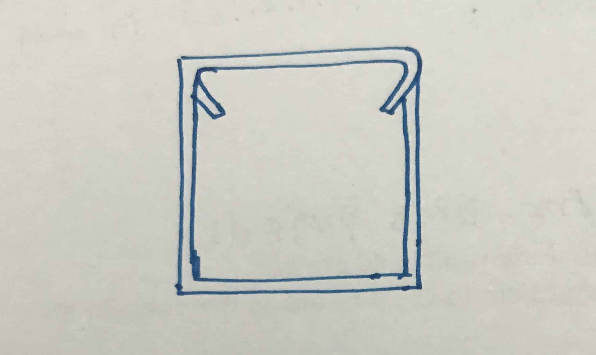
Most importantly, the torsional reinforcement members are not the same as the usual shear links intended for beams. Torsion links terminate at two ends, unlike conversational links.

Worked example for torsion beam design
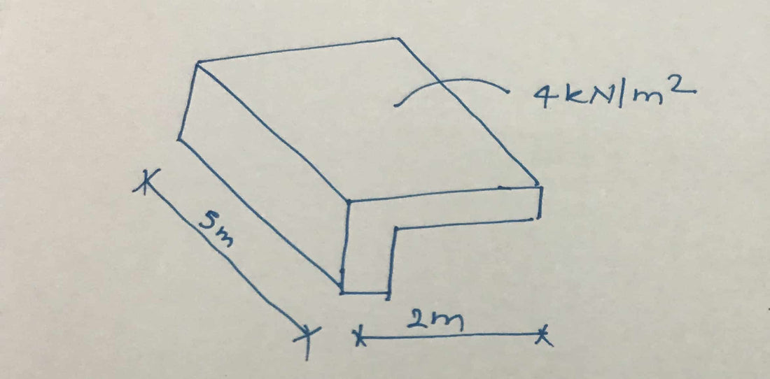
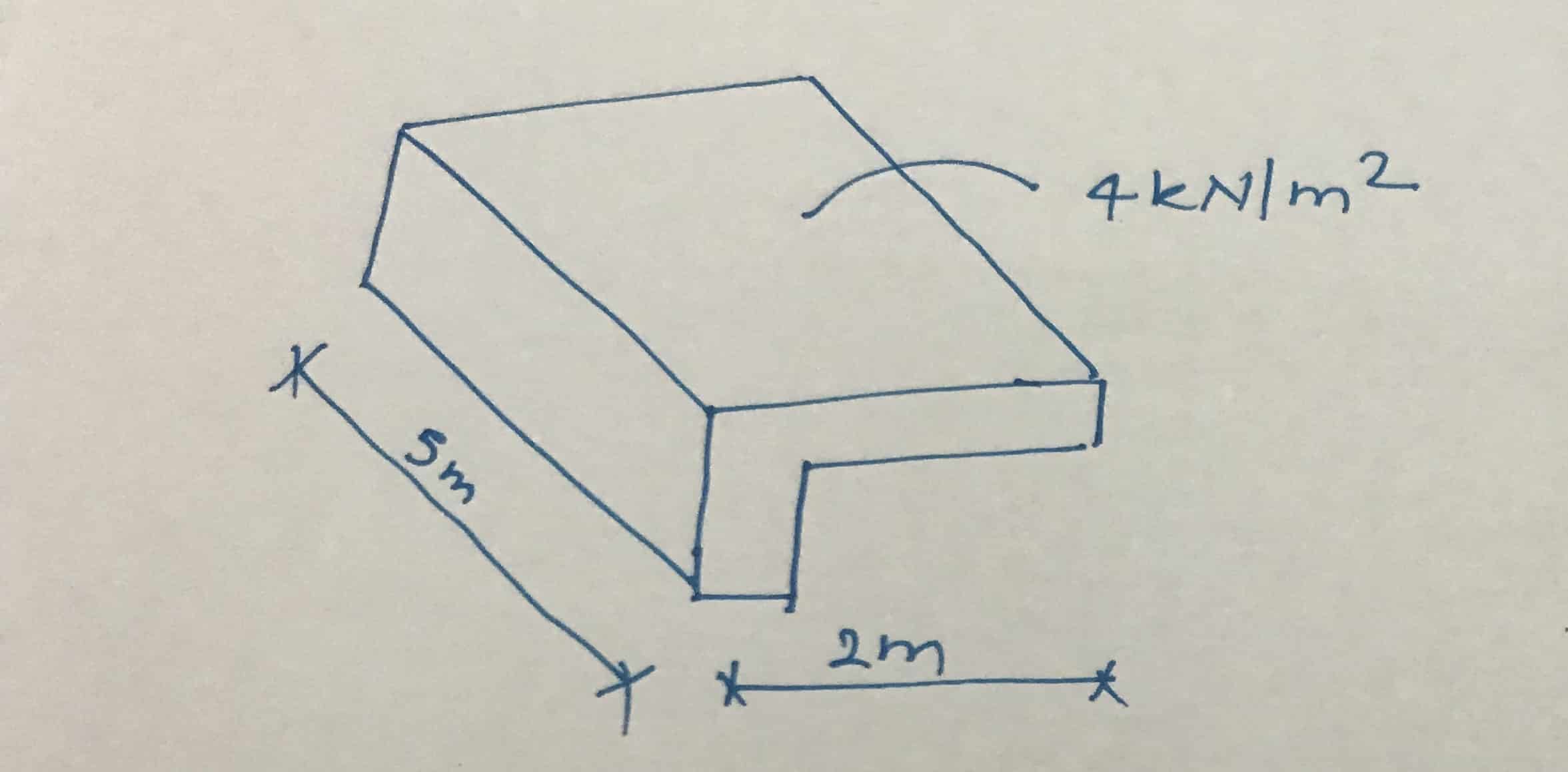
- Beam span = 5m
- Cantilever arm span = 2m
- Beam height = 600mm
- Beam width = 300mm
- Shear connection diameter = 10 mm
- Coverage up to reinforcement = 25mm
- Design load on beam including all load factors = 4 kN/m 2
- Concrete grade C30
- Characteristic yield strength = 460 kN/m 2
Calculation of torsional bending moment
Bending moment = 4 x 2 x 5 = 40 kNm
Bending moment per support = 40/2 = 20 kNm
Calculation of torsional shear stress, v T
against T = 2T/(h Minimum 2 (H Max -H Minimum /3))
T = 20kNm, h Minimum = 300, h Max = 600
against T = 2x20x10 6 / (300 2 (600 – 300/3)) = 1.24 N/mm 2
From Table 2.3 of BS 8110 Part 2,
against cumin = 0.36 N/mm 2 and V u = 4.38 N/mm 2
against cumin
In this example, we will not design the beam for shear and bending. However, for this design we need to know the shear stress and shear capacity of the beam. So let's assume some values for the shear stress.
Let's say v = 0.25 N/mm 2 and V against C
Based on the shear and torsional reinforcement requirements, there are two segments in the beam.
- against T ≤v cumin The nominal shear reinforcements are sufficient and it is not necessary to design the beam for torsion.
- against T >v cumin Design for torsion scissor links.

We can easily calculate the segment as we only need the nominal shear connections.
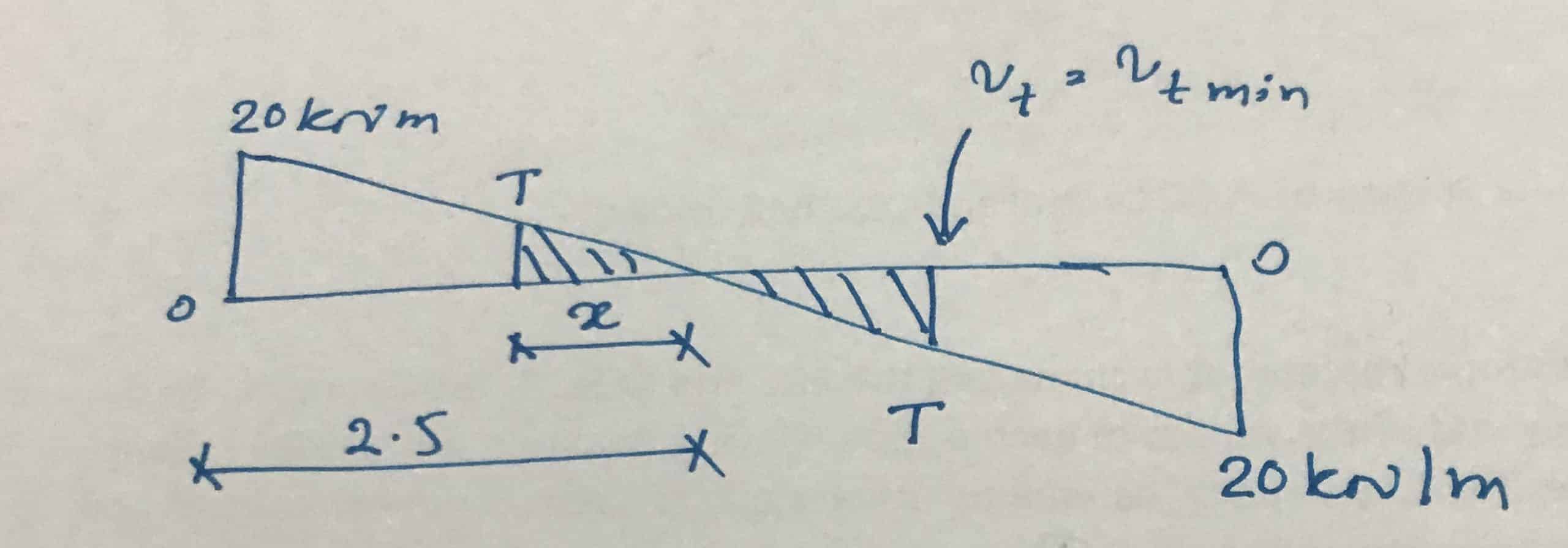
Let's first calculate the torsional moment, which determines the minimum requirement for torsion bars.
T = v cumin H Minimum 2 ((H Max -H Minimum /3))/2
T = 0.37 x 300 2 ((600 – 300/3))/2 = 8.33 kNm
Now let's calculate the distance to this moment
Suppose it is x.
x = (8.33/20) x 2.5 = 1.0m
For this reason, torsion connections must be provided at a distance of up to 1.5 m from each support.
Calculation of nominal shear connections
A SV /p versus ≥ 0.4b/0.95f jv
Consider T10 bars = 78 x 2 = 157mm 2 * two legs, therefore reinforcement area multiplied by 2; (78×2).
S against ≤ 157 x 0.95 x 460 / (0.4 x 300) = 575 mm
Provide a nominal spacing between shear joints of T10 to 250 mm. This also meets the minimum requirements for shear connectors.
Calculation of torsion reinforcement
A SV /p versus =T/(0.8x 1 j 1 (0.95f jv ))

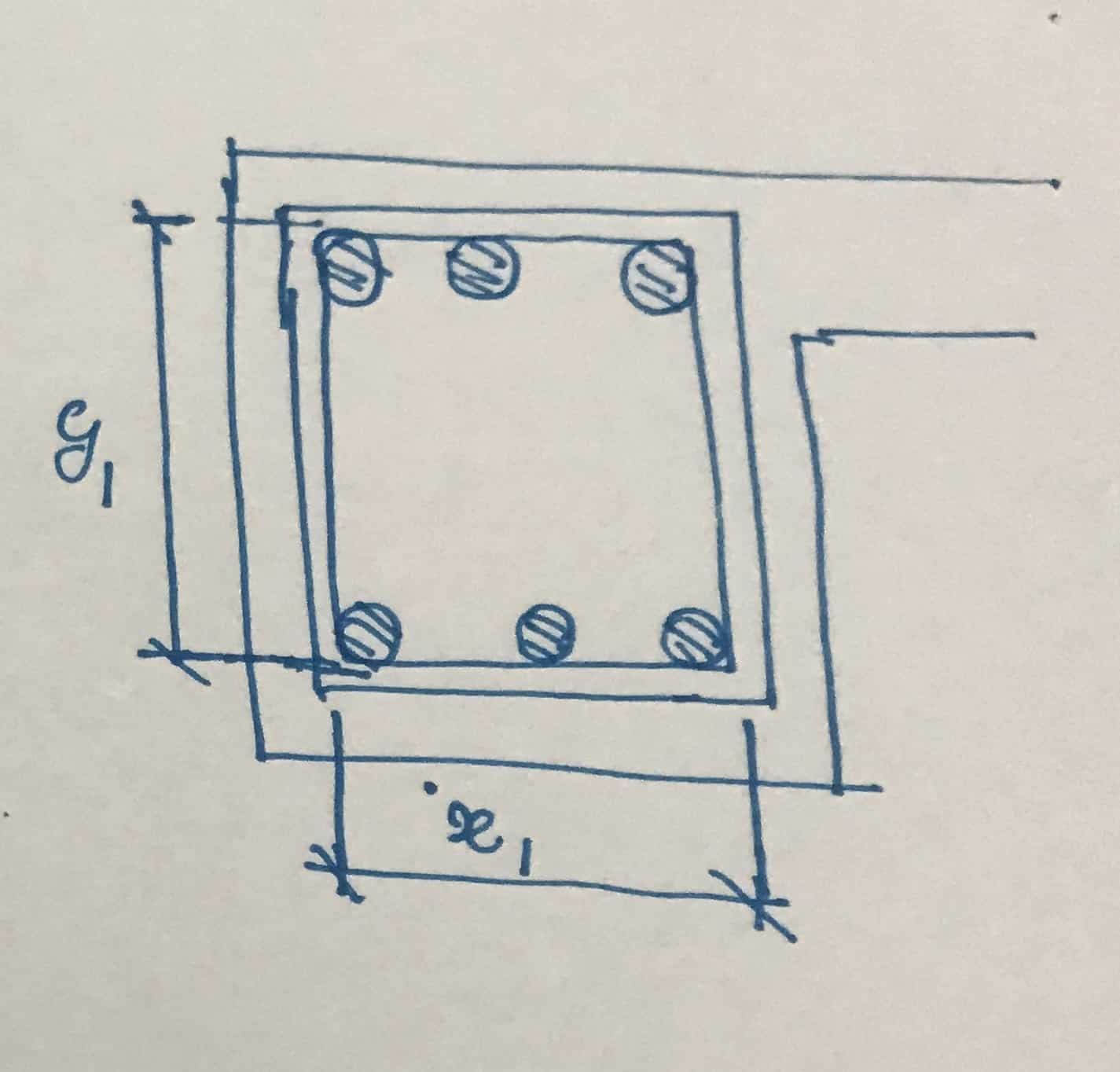
X 1 = Shortest central distance of shear connections
X 1 = 300 – 25 – 10/5 = 230 mm
X 1 = Largest central distance of shear connections
X 1 = 600 – 25 – 10/5 = 530 mm
S against ≤ 157 x 0.8 x 230 x 530 x 0.95 x 460 = 334 mm
Provides torsion reinforcement, T10 torsion scissor links with 200mm spacing
Calculation of additional longitudinal reinforcement
The following equation from BS 8110 Part 2 can be used.
A S = ON SV F jv (X 1 +s 1 )) /p against F j
A S = 157 x 460 (230 +530)) / (334 x 530) = 358 mm 2
This reinforcement area needs to be distributed at the top, middle and bottom.
Since the beam width is 300mm, we can place three beams at the top, two beams in the middle and three beams at the bottom. This results in 8 bars.
Area of a bar = 358/8 = 44.7 mm 2
We can add this reinforcement area to any of the three top and bottom bars. In between we can provide 2Q12.
In addition, we need to check the maximum torsion beam distance of 300mm and ensure that there is torsion reinforcement at all four corners.
Furthermore, we must remember that torsional bonding is not the same as normal shear bonding.