The type of connection to use depends on the type of structure and construction of the structure. Compared with other connections, moment connection is inevitable in steel structures. It is a very important and useful type of connection.
Two types of connections can be observed in a steel structure.
- Connections of the moment
- Shear connections or simple connections
The comparison of these joints is as follows.
| Moment connection | Shear connection | |
| other names | Fixed or rigid connection | Screw or hinge connection |
| Power transmission in the connection | Moment and shear | Just scissors |
| rotation | No relative rotation | Rotary connection |
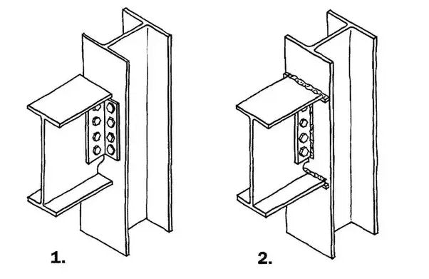
Furthermore, the connection behavior can be seen in the following figure.


The Type 1 connection can rotate freely because the top flange of the beam is unrestrained. However, in type 2 connection, the upper and lower flanges are connected to the column and do not allow relative movement. Since no relative motion is possible, this link can be viewed as a moment link.
Types of moment connections
The connection type is used to define current connections. The following connection types can be considered momentum transfer connections.
- Bolted connection between end plate and bracket
The arrangement of the end plate is key to transferring the moment from the beam to the column

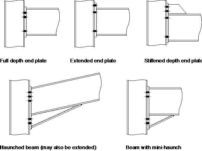
Image from stahlbau.info
- Tab connections on beams and supports (bolted cover plate tabs)
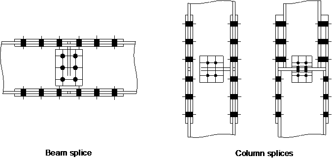

Image from stahlbau.info
- Tab connections on beams and supports (bolted end plate tabs)

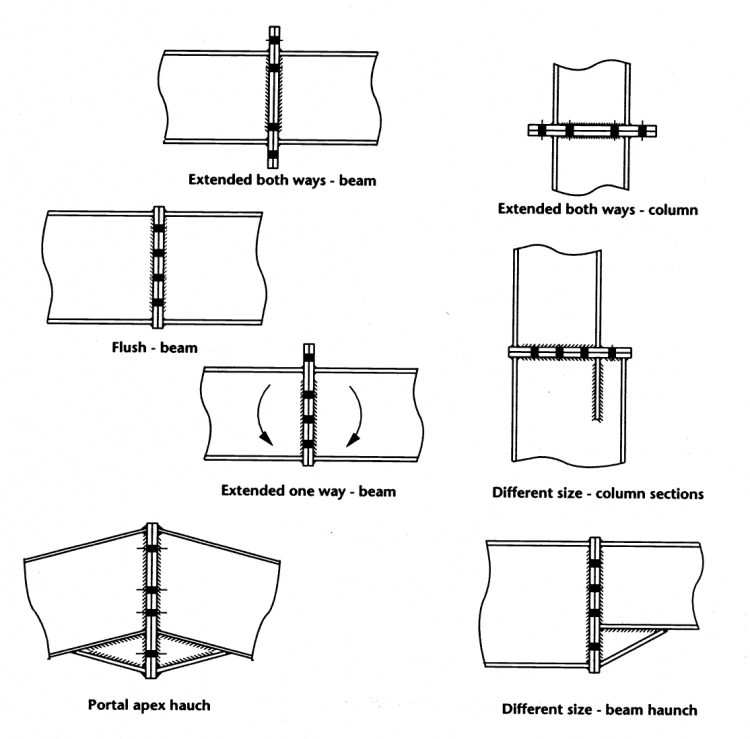
Image from stahlbau.info
- Welded connections

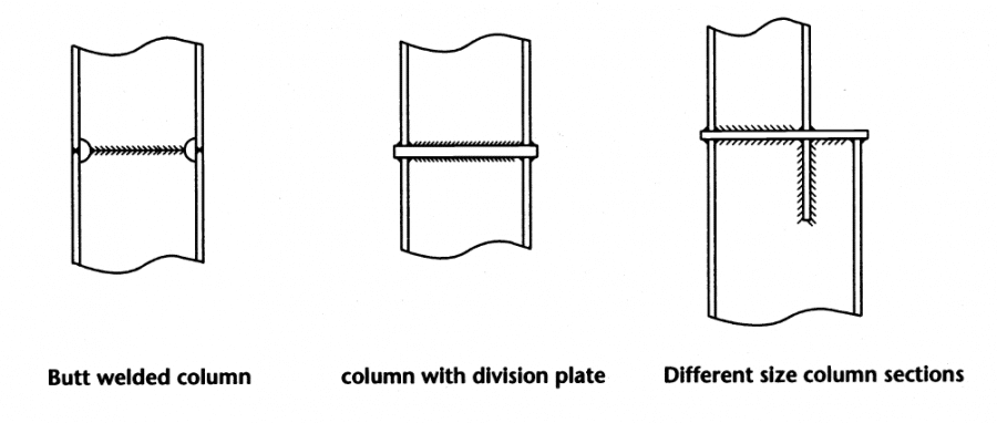
Image from stahlbau.info
- Column base plate connection


Moment Connections Project
With a moment connection, we transfer all the moment to the other element. Relative rotation is not taken into account. The calculation moment is taken into account to calculate the length and size of the weld. Furthermore, the compression and tension forces of the screw can also be calculated depending on the applied force.


The image above shows the Triangular distribution of the force due to the induced bending moment. Taking into account the balance of the connection, the bolt tension forces can be calculated.
If the ductile behavior of the connection is taken into account, full strength can be achieved. If the connection is ductile, Plastic distribution be taken into account. In this case, the tensile forces of the two screws indicated in the figure above are considered equal.
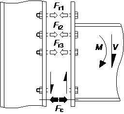

Image from stahlbau.info
After we calculate the screw forces, the screw diameter and quality can be selected. In addition, the connection board must also be checked.
Methods for Strengthening Moment Connections
To increase the load capacity of the moment link and prevent failure due to induced stresses, reinforcing plates are added to the moment link.
The following type of column reinforcement plates have been added.
- Full-depth and partial-depth horizontal bracing
Objective: Avoid web tension errors, improving flange bearing and improving web compression.
- Additional multiwall boards
Objective: Improve the tension, compression and shear capacity of the web.
- Diagonal reinforcements (Type N and Type K) and Morris reinforcement
Purpose: Improve web tension, flange bearing and web shear.
- Flange Support Plates
Purpose: Strengthen the flange bearing.
Welding Torque Connections
Instead of bolted connections, welded connections can also be used as a full torque transfer connection. A combination of threaded and welded connections is also possible.
The behavior of the fully welded connection is not the same as that of the screwed connection. The stresses induced in the flange and the column web could be equal and the reinforcement plates described above could be used to reinforce the section.
The type and size of the weld can be determined based on the applied stresses. Since the weld length for the connection between the end plate and the column flange is fixed, the weld size can be increased as needed.
When using welded joints, special attention must be paid to the quality of the weld, as it depends solely on the quality of the weld.
Below are some related articles on steel structure design.
- Single angle design for tensile stress according to EC3
- Dimensioning of screw connections according to Eurocode 3
- Practical example of constructing a single-angle section
- Design of metallic pillars according to EC3 – worked example
- Steel column design according to Eurocode 3
- Worked example of constructing a steel beam (universal beam)
- Bending and torsion (theory and calculation)
- Steel beam construction to BS 5950
- UB section classification according to BS 5950