Summary:
This article aims to make readers explore how the speedometer works in modern cars. Here you can get an idea of the CAN Bus that is used in the Communication of Sensors, Actuators and Controllers in a car.
Controller Area Network or CAN protocol is a communication methodology between various electronic devices such as engine management systems, gear control, active suspension, ABS, airbags, lighting control, air conditioning, central locking, etc. For more learnings, check this article.

Fig. 1: Arduino-based speedometer prototype using CAN interface
Description:
Prerequisites and equipment:
You will need the following:
-
Two Arduino boards or Arduino clone (here's a guide if you need it)
-
A 5v TTL-UART Bluetooth module.
-
LCD, Proximity Sensor, DC Motor and Servo Motor.
-
Arduino IDE for programming.
-
Two CAN Tranciever.
Here to simulate motor RPM measurement, we are using an industrial proximity sensor used to measure the speed of rotating objects and a DC motor whose speed is controlled by the Preset.
Inductive proximity sensor:
For non-contact detection of metallic targets at distances less than 50 mm (2 inches), inductive proximity sensors are mainly used. These sensors have a detection area where an alternating electromagnetic field is emitted. When a metallic target enters the detection area, eddy currents are induced in the target, which results in a change of state at the sensor output.
Here the sensor output will be high when a metal is placed close to the sensing area and vice versa. Using this we can make an arrangement that provides only one high pulse for each revolution of the engine. Counting the pulses for a minute can give you the revolutions per minute.
Speed measurement:
This project uses an inductive proximity sensor to detect the presence of a metal. Whenever a metal comes close to the sensor, it can detect it. Consequently, this type of sensor can be used to do many things. For example, if we need to detect when a door is closed, we can attach metal to the door and the sensor to the door frame. Whenever the door closes, the metal is close to the sensor and we can detect that the door is closed.
This same principle can be used to make a speedometer for a bicycle or any other non-contact vehicle by fixing a metal on the wheel and a sensor is placed somewhere on the frame of the bicycle, the time required for one revolution can be measured by counting the interval time between the two detections.
The setup is done as follows, a screw is connected to the rotating part of the engine and is projected a small distance. The motor is powered by 12V power supply.
The signal becomes high when the screw is close to the sensor placed near the engine.
The numbers…
RPM = 60000000/timerrevCalc;
Where:
60 = seconds in a minute.
Duration = amount of time in the detection area exposed to metal in the US.
1.4574 = the metal notch is 1.4574 times smaller than the rest of the wheel, this number needs to be calculated and adjusted per application.
60000000 is a conversion from nodes to simple seconds.
This appears to be VERY fast on the RPM reading. RPM is calculated with EACH pulse. So instead of using an interrupt and having to wait the interrupt interval to update the data, the data arrives after each pulse is timed. Also, when using interrupts you have limited resolution. Example, 1 pulse counted in 250 ms, so 4 pulses per second or 240 RPM and 2 pulses per 250 ms, so 8 pulses per second or 480 RPM!!! 1 increase in pulse will lead to an increase of 240 RPM. To get better resolution, you need a longer interrupt interval. But at the same time, longer interruption intervals will lead to slower response.

Fig. 2: Image showing CAN Bus connections with Arduino-based speedometer
Connections for Arduino and Sensor on the TX side:
The sensor used here has three wires where Red and black are VCC and GND and the Green wire is the sensor's Digital output. As stated previously, the output will increase when the metal is close to the detection area.
The sensor's VCC is connected to 5V. The GND of the sensor is connected to the GND pin of the Arduino. And the Vout or Digital output of the sensor is connected to the Arduino interrupt pin (pin 2).
Running the program:
Load the TX.ino program after saving it on your computer and open it in the Arduino IDE.
-
Compile the program in the Arduino IDE
The following function is used to send the values to the CAN bus. Detailed instructions can be found here.
CAN.sendMsgBuf(0x70,0, 2, stmp);
Receiving CAN data and displaying on an LCD on the RX side:
Load the RX.ino program after saving it on your computer and open it in the Arduino IDE.
-
Compile the program in the Arduino IDE
The following function is used to receive values from the CAN bus and display them on an LCD. Detailed instructions can be found here.
CAN.readMsgBuf(&len, buf);
Uploading software to Arduino:
If you are new to Arduino, you can start here. You should start with the Arduino IDE (Integrated Development Environment). Download the code from the link below and upload it to the Arduino board.
The system works as follows:
-
The DISPLAY processor that waits for the current RPM message sent by the COLLECTOR processor over the CAN bus.
-
The COLLECTOR processor measures the RPM, formats it and sends it to the DISPLAY processor via the CAN bus.
-
The DISPLAY processor reads the message from the CAN bus and displays it on the LCD which is repeated.
Hardware assembly:

Fig. 3: Image showing the sensor assembly on the DC motor to detect its rotational speed

Fig. 4: Image showing the inductive proximity sensor connected close to the motor assembly

Fig. 5: Image showing the Inductive Proximity Sensor wiring

Fig. 6: Typical image of Inductive Proximity Sensor
Make the circuit as shown in the circuit diagram. Make the circuit with the selected parts and connect the motors to the circuit.
Circuit diagrams
| Circuit Diagram-Speedometer based on Arduino using CAN interface | 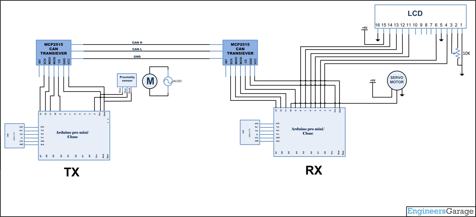 |