In recent years interest in Unmanned Aerial Vehicles ( UAVs ) and their use for an ever-widening range of applications has grown tremendously. This type of aircraft can be controlled remotely or programmed to fly autonomously. They have been used for different types of applications as individual entities in both military and civil tasks. Research related to this type of systems is being carried out in many areas, from the design of more efficient aircraft aimed at specific applications, to the development of improved control electronics that provide better autonomous behaviors, to optimized route planning strategies, or the opening of new areas of application. Currently, a whole new field of research is opening up in the area of coordinating UAV teams to cooperatively carry out different missions. This field is still in its infancy and many new and interesting approaches are being explored for different applications. Examples of these are work related to trajectory planning in UAV teams, real-time target tracking and many others.
The shrinking size and increasing capabilities of microelectronic devices in recent years have opened the door to more capable autopilots and driven more real-time Unmanned Aerial Vehicle (UAV) applications. Payload Directed Flight (PDF), a research task of NASA's Aeronautical Research Mission Directorate, Fundamental Aeronautical Program, Subsonic Fixed-Wing Project, aims to address this by developing a set of capabilities in both hardware and software that enable such applications in real time. Specifically, payload directed flight research examines sensor- and payload-centric autopilot modes, architectures, and algorithms that provide layers of intelligent guidance, navigation, and control for flight vehicles to achieve payload sensor-related mission objectives. useful by taking into account various constraints such as aircraft performance limitations, target tracking and estimation, obstacle avoidance, and constraint satisfaction. The central problem addressed by PDF is the control of a known and controllable plant interacting with an external system based on payload and sensor data feedback that provides partial observation and understanding of the external system, to satisfy mission objectives and constraints. of the combined system.
With progressive battlefield success in Operations Desert Storm, Allied Force, Enduring Freedom and Iraqi Freedom, Unmanned Aerial Vehicles (UAVs) are capturing the imagination of militaries around the world. The specter of Iraqi UAVs with a range capability of over 300 miles carrying chemical/biological weapons was described by US Secretary of State Colin Powell in his February 2003 remarks to the UN Security Council.
LITERATURE SEARCH
Small unmanned aerial vehicles (UAVs) can be deployed on the front lines of combat to provide situational awareness to small units of troops through real-time information about surrounding areas.1 Small unmanned aerial vehicles and fixed-wing microvehicles ( such as the Dragon Eye, Aerosonde, Hornet and Wasp) have become prevalent and demonstrated impressive flight capabilities and levels of autonomy.2 These UAVs can weigh as little as a few grams. However, even the lightest models must fly fast enough to provide enough lift for flight. These fixed-wing aircraft also require room to turn and although research has studied their ability to fly in small circles over a specific area, they are difficult to fly in confined locations such as urban environments and small indoor spaces.
Rotary-wing unmanned aerial vehicles have the potential to be very useful if they can hover and fly vertically.
Currently, VTOL UAVs such as the Fire Scout and Hummingbird have the ability to fly autonomously, land at a specific location, and take off again. Smaller UAVs with these capabilities would have many applications, including flying through buildings for search and rescue or surveillance operations.
However, technical challenges for small rotary-wing UAV systems are numerous. High thrust-to-weight ratios are required for the propulsion system. Endurance long enough to carry out a significant mission will also be important. A careful combination of batteries, electric motors and rotors will be essential; and these will have to be sized to carry the required payload. Incorporating a reliable semi-autonomous control system into these small vehicles, so that the operator does not have to constantly monitor their performance or location, will be a major challenge, as they will only be able to carry the smallest microprocessor systems and power supplies. along with very lightweight and inexpensive sensor systems. Additionally, a Global Positioning System (GPS) will not work indoors, so other sensors will have to be used for indoor flights. The software must be very compact to fit into the available memory, but powerful enough to provide intelligent control with sensor data of limited quality.
THEORETICAL DETAILS AND ANALYSIS OF THE TOPIC
The Project consists of 3 sections.
} · Model Aircraft Section
· Electronic Section
· Communication Section
Model Aircraft Section:
This section consists of the design part, i.e. the general structure of the Drone, the
thrust vectoring mechanism design, choice of propellers to achieve the required thrust-to-weight ratio, servo linkage design, engine assembly, component positioning, etc.
Electronic Section:
This section includes the design of the power supply and distribution mechanism. We also consider various factors such as power consumption, maximum thrust and RPM before selecting BLDC engines as the main propulsion engine. The Brain of the UAV is its flight controller system which consists of the Atmel 324 (kk2) or atmel 328 (HK) processor, gyroscope and accelerometer sensors that form the Inertial Measurement Unit.
We use and compare two types of IMU boards, viz.
1. Hobbyking v3 quadcopter control board.
two. KK2.0 multirotor control board.
Communication Section:
To control the UAV remotely, we are using a 6-channel transmitter-receiver pair that uses ISM band spectrum (2.4 GHz) for communication.
The transmitter transmits PPM signals using Frequency Hop Spread Spectrum which are decoded by the receiver to form PWM signals of time ranging from 1ms to 2ms and frequency of 50Hz.
To achieve real-time audio/video transmission, we can use DVR compatible transmitter-receiver and 1/3” PAL CCD camera. There are various versions available with transmitting frequency like 900 MHz, 2.4 GHz, 5.8 GHz, so if you are using a 2.4 GHz transmitter, do not use a video transmitter of the same frequency as it will cause interference and will cause a crash.
In this project we use a small keychain camera that records video on an SD card (without RTVT).
Note: This project is related to RC hobby which is an emerging hobby in India and there are not many Hobbyists in India at the moment.
So if you want to know about this hobby, the basics of Rc plane, Rc car, etc. go through these links.
Communication Section
In the communication and electronics section we will be using practically products available on the market and we will not do anything except in the model aircraft section.
Now for wireless control of our UAV we will need a transmitter and a receiver.
Now this section might be too big if I try to do a comparison of all the Txr-Rxr available on the market, or try to make one, but it's not feasible, so we'll use a Txr-Rxr pair available on the market.
These Txr-Rxr pairs are not a simple infrared transmitter or some kind of decoder and encoder that you might have used in some robotics project. These pairs are specially made for RC hobbyist use to control planes, helicopters, cars, etc.
I'm also a beginner in this field and have yet to fly an RC plane successfully.
This Txr-Rxr pair uses free unlicensed bandwidth for communication.
Previously the 75 MHz frequency was used, but now everyone has switched to 2.4 GHz systems as it is the free and unlicensed frequency band allocated by the government.
The 2.4 GHz Txr-Rxr pair uses spread spectrum technique which makes them resistant to interference and provides fault-free operation. Some use FHSS technology, some use DSSS technology, and some use hybrid FASST (FHSS+DSSS).
Now the most important point, the price range of the radio varies from Rs. 2,000 – 20,000 depending on the features offered by the radio. Expensive, high-end radios provide programming and saving different settings for different models without needing to connect to a computer. They also provide some type of telemetry where the amount of battery remaining in your plane is displayed on the Txr screen.
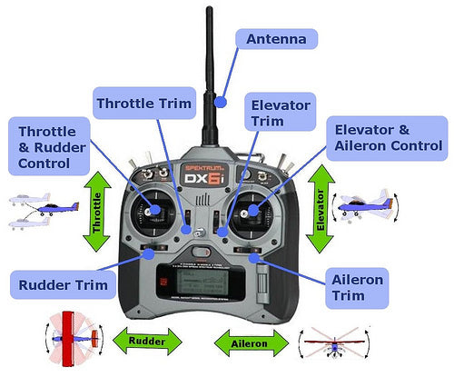
Transmitter Basics
Transmitter Basics:

Basic radio terms:
Throttle Stick: The throttle stick will change engine speed.
Aileron: The aileron stick will induce roll in the aircraft.

Elevator: will provide aircraft tilt control.

Rudder: this stick gives yaw control.
Channel : These are the control channel numbers on your Txr-Rxr pair, for example. In 6 channel radio you can connect 6 servos or 6 motors or some motors and servos to the receiver whose total number will not exceed 6.
These six channels in the receiver are connected to the transmitter sticks and provide a pwm signal of 50 Hz frequency with a time pulse of 1ms to 2ms (this same signal is used to drive the servo motor).
Mode : There are 4 transmitter modes available, namely Mode1, Mode2, Mode3 and Mode4.
These modes are nothing more than the placement of the aileron, elevator, etc. channel control. on the transmitter handles.

CH1= Aileron CH2= Elevator
CH3= Throttle CH4= Rudder
Receiver signals
Receiver signals:
The transmitter usually transmits PCM or PPM signals which are received, unscattered and decoded by the receiver and we obtain PWM signals on corresponding channels like those of the transmitter. These PWM signals have a frequency of 50 Hz (time period of 20 ms) and the pulse activation time varies from 1 ms to 2 ms.
For example: if I move the aileron stick on my transmitter, the pwm signal on channel 1 will vary depending on the position of the stick.
These pulses mean acceleration signal for BLDC motor and shaft position for servo motor.
|
Just in time |
BLDC motor speed |
Servo axis angle |
|
1 millisecond |
Minimum or zero acceleration |
0 0 |
|
1.5 milliseconds |
Half throttle |
90 0 |
|
2 milliseconds |
Full throttle |
180 0 |
We connect the signal to the DSO to observe the waveform.
You can see that the wave frequency is 45.5 Hz, the activation time on the mid stick is 1,550 ms and 1,850 ms at about 75%.

75% stick

Intermediary
If you already have a radio, then you should be well familiar with all the above basics and be able to use your radio with the UAV.
If you are a beginner, I recommend that you buy the Flysky CT6B Radio as it is the cheapest available and also works satisfactorily, it can also be programmed on a PC and can also be used as a simulator.
In this project I used FLYSKY CT6B radio .


Specifications:
Channels: 6 channels
Frequency: 2.4GHz
RF Power: Less than 20db
Modulation: GFSK
Code Type: PCM
Sensitivity: 1024
DSC port: yes
Charger port: yes
Power: 12V DC (1.5 AAA * 8)
Ant length: 26mm
Certificate: CE FCC
If you can see, there are a total of 7 rows and 3 columns on the receiver. These lines are channel1, channel2 up to channel 6 and an extra line is for connecting the battery to the receiver and is also used for a process called bonding.
1 st column (the internal one) provides the PWM signals corresponding to the position of the stick on the transmitter.
2 and column (middle) is the Vcc power pin. 3 third column (outer) is the ground pin.
In an RC plane, the brushless motor is connected to channel 3, the aileron servo is connected to channel 1, the rudder and elevator servos are connected to channel 4 and channel 2 respectively.
But we are not making an RC plane in this project, so the connections would be worked out later.
The second thing in the communication section is the FPV (First Person Videography) camera.
I didn't use them on this project because we didn't have the budget.
Electronic section
Electronic section:
Parts in the electronic section:
Brushless motor
servo motor
Battery
Control Panel
“ Selecting the engine for your UAV
As we are manufacturing a UAV that will have IMU sensors, it is recommended to reduce vibrations to the minimum possible, otherwise there will be a lot of noise at the sensor output and
you will get unexpected behavior from your UAV. To reduce vibrations you must
1. Mount the IMU sensors on vibration dampening materials such as double-sided tape, nylon spacers, foam, etc.
2. Reduce vibrations from vibration-causing agents
Our BLDC motor will be the main vibration causing agent in our UAV, so we have to choose a motor that provides minimum vibrations
We should choose lower RPM motors below 1000KV for lower vibrations.
Engine selection:
One of the important parts of the multirotor is its engine. It is part of the energy system. In fact, the entire power system depends on the engine selection, so you must be very careful when selecting the engine. We use Brushless motors for multirotor. The brushless motor comes with some important specifications. You will see these specifications on the page if you are purchasing online. So this simplifies our work. For engine selection, some important specifications are.
kV
Maximum current(A)
Shaft diameter
Impulse
Weight
Lipo(3S-4S)
Suggested support
For multirotor applications, 600-1200kV motors are good. Below 600 kV even better. Low kV means you can swing a big propeller. Big propeller means it can move more air and you will get more thrust.
kV = RPM/V
If you have a 600kV motor and a 3S battery to supply power, the NO LOAD motor RPM would be:
600 x 11.1 (3S battery) = 6660 RPM.
Maximum current rating is another important factor when selecting the motor. ESC and battery selection depends on this value (we will learn later). It should be able to work with 3S and 4S lipo battery. Shaft diameter helps select bracket adapter. Now we're getting to the thrust. In most cases, you will see the amount of thrust the engine can produce with the propeller suggested on the website. If you remember, we learned that to lift 1,000 grams of quadcopter, we need a total of 2,000 grams of thrust. And the quadcopter has 4 engines, so each engine must be able to produce at least 500 grams of thrust to satisfy our need.
4 engines x 500 grams of thrust = 2,000 grams of thrust.
One more thing is Watt.
Watt = V (Voltage) x I (Ampere)
More Watt, more power, so you should also consider this when selecting the motor.
But when it comes to selecting the motor, you will notice that there are many options available for motor selection and it is really confusing, so which motor is best for multi-rotor application? Well, you have to consider a few more things besides the specifications. Some of them are
Motor Mounting: Well, motor mounting is yet another important factor that you should keep in mind while selecting the motor for your multirotor. The engine mount comes under pulling force especially when you are swinging a big propeller and if the engine is not seated properly it can come loose in flight and I'm sure no one wants to see these things happen. So, make sure that the engine you are buying has a good bracket that can hold the engine properly under heavy load and likewise you can fit this bracket easily to the frame. However, you should always check before flying that all connections and fasteners are properly fitted. Obtain a spare engine. So, I hope I covered everything for engine selection.”
-Credits
Dharmik
www.rcindia.org
The engine I used for this project is

RPM/V: 1120 Kv
Maximum Watt (W): 336
Maximum current (A): 23.2
Shaft diameter (mm): 4.0
Weight (g): 70
Motor size (mm): ?28*36
Ri ( ?): 0.070
Suggested Esc: 30 amp
Li-Po: 2-4 cells
Thrust: 1130g
You will need 2 engines as we are designing a twin rotor UAV.
When I ordered the above engine and after we were unable to successfully fly the UAV in 2 projects, it was during 3 third project that we realized that one of the engines was a little faulty, the engine's rotating can touched the base when it was in the push configuration, so we attached it to the top so that it would now pull and the friction problem would disappear.
I wouldn't suggest the same engine to you because it is not branded.
Consider the thrust provided by the engine when selecting.
When selecting an engine, you should select a branded one with good build quality.
If you are purchasing the components from Hobbyking.com or other stores, there are reviews on the same page about the products, so when selecting the motor, read the reviews and do not buy those whose customers claim to have faulty bearing or poor build quality.
Turnigy brand engines are some of the best available; I am using the Turnigy Park 450 in my RC plane and as I stated before I couldn't fly an RC plane, I crashed it so much, so many times, but still the park engine is working perfectly.
So I suggest you buy a good quality engine with more than 1 kg of thrust for this project.
Support adapters
Support Adapters:
It looks like this:

To connect the propeller to the motor shaft, we need something called a propeller adapter.
Attached to the engine like this:

And the Propeller is fixed like this:

Electronic speed controller
Electronic speed controller
As I said, brushless motors do not have brushes, they need external circuits to switch current through them, ESC is that circuit.
ESCs take DC voltage and convert it to three-phase AC voltage.
ESCs are rated based on the current they can handle, such as 10A ESC, 20A ESC, etc. I used 30A ESC for my motor, when you select your motor they will probably tell you on the product page which ESC you should use.
The rating would be written as 20-30A, 30-35A, in this the 1 st number is the continuous current your ESC can handle and 2 st number is the breakdown current. So if I say we need 30A ESC then 1st the number should be 30
Or you can see your motor's maximum amp draw on the product page and select ESC whose current is 1.5 times the motor's maximum current or at least 5 Amps more than the maximum current.
This will ensure you don't fry your ESC if the motor is even slightly overloaded.
Basic Connection Guide:

Refer to the image above, the ESC receives the DC voltage from the battery and according to the signals they receive from the receiver (remember the PWM signal), they change the switching frequency of the output three-phase AC signals, thus changing the speed of the BLDC engine.
You can connect the three ESC wires to the BLDC wires in any way, with no specific polarity.
However, after connecting your motor to the ESC, if your motor rotates in the reverse direction of the desired direction, swap any 2 wires of these three wires to change the direction of the motor.
ESC I USED: Redbrick 30A ESC
Specifications:

Maximum Amps: 30A
Ubec: 5v/2A
Cells: Lipolysis 2~3s
Size: 52mm x 14mm x 25mm
Weight: 22g (Wires Included)
We will need 2 ESCs as we are using 2 BLDC motors.
Servo motor Specifications:
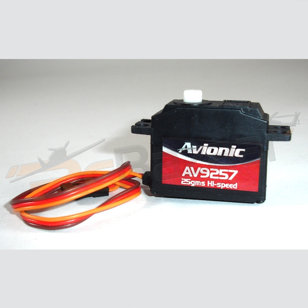 Wire length: 18cm
Weight: 44 grams
At 4.5V
Speed (sec/60): 0.08
Torque (Kg-cm): 2.0
At 6V
Speed (sec/60): 0.07
Torque (Kg-cm): 2.2
We need 2 servos for our two control surfaces, i.e. pitch and roll.
Propellers
Propellers:
"PROPELLER
We always neglect this plastic part. Just because it's cheap? Who knows!! But in multirotor applications the contribution of the propeller is notable. The bracket specifications are easy to understand and are diameter and pitch. The type of propeller is also important, but we will look at the effect of diameter and pitch on multirotor flight. We usually see prop with the specification of
7×3.5
8×4.5
9×5
10×3.8
10×4.5
10×6
11×4.7
12×3.8
The first value is the diameter of the support and the second value is the pitch. Both are in inches.
Diameter: Virtual circle that the support generates/or the total length of the support.
Step: Number of trips per revolution.
As we can see above, our engine runs at 6,660 RPM without load. But when you mount the bracket on it, the RPM will be reduced. Here we will take the example of two props 10×3.8 and 10×6. When you mount a 10 inch diameter bracket, the engine RPM will be reduced to 3600 RPM (revolutions per minute).
60 revolutions per second.
Our first bracket has a 3.8-inch pitch. Meaning per revolution it will travel 3.8 inches. Then
60 x 3.8 = 228 inches/sec = 5.7 m/sec
For the second support, it has a 6-inch pitch.
60 x 6 = 360 inches/sec = 9.1 m/sec
Therefore, we can say that if we have a 10×3.8 propeller our quad bike will rise into the air at 5.7 m/sec, while with a 10×6 propeller the rate of rise will increase to 9.1 m/sec.
A larger diameter bracket can produce more thrust.
So which propeller is best for our multirotor?
Generally you will get the suggested value in the engine specification, so you should go ahead and buy 1-2 extra pairs. But what if the proposal value is not provided. You will see a sort of table with different props, Volts, Amp, Boost and Efficiency. Here you will have to try the trial and error method. But that doesn't mean you swing the 13×3.8 propeller on the 1700kV motor.
The lower kV motor can handle larger propellers. With increasing kV value, the helix size will decrease. So you will have to keep that in mind. For multirotor you should use low pitch propeller if you need more stability and less vibrations. How to balance support? We’ll see in the next part.”
-Credits
Dharmik
Rcindia.org
Accessory selection
In this project I used a 10×4.5 2-blade propeller, as well as a 10×6 3-blade propeller.

And remember that you have to buy a pair of these supports, that is, one support must be clockwise and the other counterclockwise.
In the photo above you can see small rings, they are known as propeller adapter rings, they are inserted into the propeller so they can fit all sizes of propeller adapters.
Why pair??
As you will see, we will mount the two motors coaxially, one below the other.
A motor will rotate clockwise, thus inducing counter-torque in a counterclockwise direction. If we don't cancel this counter torque, as soon as our UAV takes off, it will start to rotate counterclockwise.
This is the reason why there is a second fan in the tail of the helicopter, to cancel the countertorque.
In our UAV there is no tail fan, so we will mount another motor and rotate it counterclockwise so that the induced torque is clockwise, so if the counter torque induced by both motors is equal, they each other will be canceled and the UAV will be stable, this is called yaw control. Plus, we'll get more thrust than using just one engine.
Lithium Polymer Batteries
Lithium Polymer Batteries
Voltage and cell count:
Lithium polymer batteries use a set of lithium polymer cells.
Each cell has a nominal voltage of 3.7 V, a fully charged voltage of 4.2 V, and a minimum voltage of 3.0 V.
If we connect two cells in series we will get a 7.2V Lipo Pack and the pack would be known as 2S pack.
Similarly, the voltage on the 3s pack would be 11.1V.
When charging you must use a charger made especially for lipo batteries.
Classification C.
How quickly a battery can discharge is its maximum current capacity. Current is usually rated at C for the battery. C is how long it takes to discharge the battery in fractions of an hour. For example, 1 C discharges the battery in 1/1 hour or 1 hour. 2 C discharges the battery in ½ or half an hour. All RC batteries are rated in milli Amp hours. If a battery has a capacity of 2000 mAh and you discharge it at 2000 mA (or 2 amps, 1 amp = 1000 mA), it will be completely discharged within an hour. The C rating of the battery is therefore based on its capacity. A 2000mAh cell discharged at 2 amps is being discharged at 1C (2000mA x 1), a 2000mAh cell discharged at 6 amps is being discharged at 3C (2000mA x 3).
All batteries have limitations on how quickly they can discharge. Because of this, many LiPoly batteries are placed in parallel to increase the battery's current capacity. When 2 batteries are connected positive to positive and negative to negative, they become like a battery with twice the capacity. If you have 2 2000 mAh cells and connect them in parallel, the result will be the same as 1 4000 mAh cell. This 4000mAh cell has the same C rating as the original 2000mAh cells. So, if the 2000mAh cells can discharge at a maximum of 5C, or 10 amps, then the new 4000mAh cell can also discharge at 5C, or (4000mA x 5) 20 amps. This method of battery construction allows us to use LiPoly batteries at higher currents than individual cells could produce. The naming convention that allows you to decipher how many cells are in parallel and how many are in series is the XSXP method. The number in front of the S represents the number of cells in series in the pack, so 3S means it is a 3-cell pack. The number in front of P means the number of cells in parallel. Therefore, a 3S4P pack of 2100mAh cells has a total of 12 cells inside. It will have the voltage of any other 3S package, as the number of cells in series determines the voltage. It will have a current handling of 4 times the maximum C rating of the 12 individual cells. So let's say our 3S4P package had a maximum discharge of 6C. This means it has a nominal voltage of 10.8 volts (3×3.6) and a maximum discharge rate of 50.4 amps (2100mAh x 6Cx4P).
LiPo battery selection:
When selecting LiPo batteries, we must take into account the amount of current that we will draw from the battery.
The motor I used should consume 23.2 A of current and since we are using 2 motors, the total current consumed would be 23.2 x 2 = 46.4A.
Therefore, the current consumed would be greater than 46.4A, also considering the current consumed by the servomotors.
High mAh battery, longer flight time
High C rating, more discharge rate.
Also, sometimes the rating written on the battery is not true and is lower than what is written, so we should not select marginal ratings and should opt for a little more.
Ex: in the beginning we were using a Turnigy 2200mAh 25-30C battery that should allow a discharge rate of 2200 x 25=55A, but even so, after a few flights we noticed that the battery swelled a little and with each test that passed the battery was blowing and eventually the battery capacity was reduced to the point that our UAV would no longer take off.
Therefore, take special care when selecting the battery as it is the main source of power and is also expensive.
Also do not use batteries weighing more than 300 grams.
So after we ruined our first battery, we bought this one:
Specifications:

Capacity: 3300mAh
Voltage: 11.1V
Continuous discharge rate: 25°C
Maximum explosion rate: 50°C
Settings: 3S1P
Charge rate: 1C
Size: (H)20mm*(W)44mm*(W)135mm
Weight: 247g
PVC color: Blue
Connector: XT60
Flight Control Board
Flight Control Board:
The most important component of a multirotor is the flight controller board.
The flight control board has IMU sensors with a microcontroller to perform control tasks.
Now what does this control.
A VTOL aircraft needs to be stable in 3 axes i.e. pitch, roll and yaw axes so that it can hover in the air. The IMU sensors detect the orientation of the aircraft and send the data to the microcontroller, the microcontroller processes the raw data to estimate the angles and provides error compensation to bring the aircraft back to its home position.
And it does this with incredible speed and precision, which is why we need a controller for VTOL UAVs.
There are many multirotor control boards out there like APM, Openpilot mega, multiwii, kk multicopter etc.
I used below two:
HK v3 board

Specifications:
Size: 50.5mm x 50.5mm x 23.5mm
Weight: 14.5 grams
IC: Atmega328 PA
Gyroscope: Murata Piezo
Input voltage: 3.3-5.5V
Receiver signal: 1520us (4 channels)
Signal for ESC: 1520us
Characteristics:
1. Atmega 328 controller.
The microcontroller used is the atmega 328 8bit avr controller.
two. 16-bit timers in AVR.
3. 3-DOF, gyro sensors only.
The gyroscope sensor is an IMU sensor and detects the angular velocity when the UAV is tilted. Also read about Tilt sensor
4. Analog Murata Piezo Gyro
The gyroscope sensors used are some cheap murata piezo gyroscopes, not very sensitive.
5. Setting PI gains using built-in potentiometers.
The control board has 3 integrated potentiometers to change the P and I gain of the PID controller used in the software. These gains define how many degrees of UAV tilt the control surface should tilt.
6. Can support up to 6 rotor UAVs
We can also make quadcopter (4 rotors) or hexcopter (6 rotors) using this board.
7. No self-leveling.
Since gyroscopes measure angular rate, they do not know the actual orientation of the aircraft, the only thing they do is try to avoid the tilt of the UAV.
8. Angle estimation: gyroscope only
9. No AHRS and sensor fusion.
AHRS and sensor fusion are some advanced techniques that provide very accurate angle estimation and UAV control, but they are not employed in this board.
10. No camera gimbal
It does not have a camera gimbal to stabilize the camera during flight.
11. Less subject to vibrations.
One merit is that it is less prone to vibrations because of the cheap murata gyroscopes.
two) KK2.0 board

Specifications:
Size: 50.5mm x 50.5mm x 12mm
Weight: 21 grams (Piezo Inc doorbell)
IC: Atmega324 PA
Gyroscope: InvenSense Inc.
Accelerometer: Anologue Devices Inc.
Auto Level: Yes
Input Voltage: 4.8-6.0V
AVR interface: standard 6-pin.
Receiver signal: 1520us (5 channels)
Characteristics:
1. Atmega 324 controller.
This board uses the atmega 324 avr controller, it has more UART and SPIs than the atmega 328.
two. 16-bit timers in AVR.
3. 6-DOF, 3-axis gyroscope and accelerometer.
The most amazing addition in this version of the board is an accelerometer, which makes it a 6 DOF IMU board.
4. Ultra-sensitive MEMS digital sensors.
Unlike previous Murata gyroscopes, this board uses more sensitive MEMS gyroscopes and accelerometers.
5. Configuring PI gains using LCD UI.
Another amazing addition on this board is the LCD user interface which makes configuration and also setting PI gains easier, no more need to write firmware on this board, the only thing is we have to select the UAV type and fly.
6. It can support up to 8 rotor UAVs.
Yes, we can make octocopter with this board.
7. Capable of self-leveling
Since accelerometers can determine the orientation of the UAV in space, it is now possible to have the self-leveling function on this board
8. Angle estimation: Gyro & Accel.meter.
It uses sensor fusion techniques to estimate angles using accelerometer and gyroscope data, which increases accuracy and provides better self-leveling function.
9. Uses AHRS Algo and Sensor Fusion for accurate angle estimation
It uses an Attitude and Heading Reference System, the one used in aircraft and rockets, and is the most efficient system for UAVs. It also estimates Euler angles, which is a technique for representing a body in space.
10. Camera Gimbal
We can also connect the camera to a gimbal to obtain stable aerial photographs.
11. More prone to vibrations
As it uses highly sensitive IMU sensors, it is also very sensitive to vibrations.
We will use the kk2.0 board as I tried using the HK v3.0 board with no luck.
Connection diagram:

More on how to put everything together and set up the board to work for us after the model airplane section.
Model aircraft section
Aeromodelling section:
We used depron and wooden strips to build our frame.
You can make your own design using whatever material you want, but try to make it as light as possible.
The weight of our UAVs is 1200 grams
Below are photos that will give you a good idea about the construction of the frame.

Figure : Complete
You can see the paper tape on the propeller, it serves to balance the propellers.

Figure : Top view

Figure : Control surface

Figure : FC board

Figure: Connection to control surface

Figure : background
Construction of the external structure and assembly of the engine
Building external frame
The black circular part is a sheet of depron glued to form a circle 32 cm in diameter,
It has 4 wooden pillars 29 cm high around its circumference as shown in the images below.


Motor support
We made a + support for the engine, as the engine support has 4 screws, you must tighten all the screws to avoid vibration. Also due to vibrations, the nut may start to loosen and fall out, so tighten the screws upside down, i.e. the nut on top.

Figure : Engine support

Figure : ESC
Both ESCs are on the bracket itself secured with paper tape, you can change the positioning of the ESCs to balance the weight of the UAV at the end if it appears unbalanced.
For us, the above position worked well.
Servo and connections
Servant
Servos are used to move the control surface; we have two control surfaces, so two servos will be needed.
Note the position of the servos on the UAV, the position.

Also select the diameter of the support and offset cylinder carefully, otherwise the clearance between the propeller and the servo would be very low.

Connections
To transfer the angular displacement from the control axis to the control surfaces we will need the connections.
The linkages will first convert the circular displacement of the servoshaft into linear displacement and then back into angular displacement of the control surface.
Therefore, we connect the link rod using hinges to the servo horn and control surface shaft.

You can design a linkage if you want different control surfaces and servo deflection.
Here is the formula to calculate this:

You can see x and y in the image above. q x is the angle deflection of the control surface and q y is the angle deflection of the servo horn.
If you want high control surface deflection for low servo horn deflection, select x
In our case we select x=y=1.5 so our q x = q u.
Select x>y if you have a high torque but low speed servo and y>x if you have a low torque but high speed servo.
Control surface design
Control surface design
You can use the formula below to calculate the length (width) of the control surface chord for a given servo torque or vice versa.
The mathematical model: “t = (AMPC2LV2) / (4RT)” where:
t = servotorque
A = sin(S) * tan(S) / tan(s)
S = angle of control surface in relation to neutral
s = angle of the servo arm in relation to neutral
M = molecular weight of air (~28.6 g/mol)
P = air pressure (1 atm)
C = average control surface chord length
L = average length of control surface
V = air speed
T = air temperature (~290 K)
R = ideal gas constant (82.056 atm cm3 / mol K)
Or use our design:

In the CAD image below you will get a better idea of the shape of the control surface.


We made a control surface out of coroplast and inserted thin metal rods and glued them with bondtite.
One side will have a stop as above and one side will be connected to the servo via linkage as already discussed.

The clearance between the lower engine and the control surface is 1 cm.
Similarly, there is a gap of 1.5 cm between the motor and the FC board assembly as shown below

The length of the control surface we used is 30 cm. and the height of this control surface is 5.5 cm.
The angular cut-off between the rotation and tilt control surface is 45 0 so there must not be any type of contact between the two control surfaces.

FC board mount design
FC board mount design
The FC card bracket is screwed 1.5 cm above the top motor. The holder is a rectangular strip of wood that holds the Lipo battery and FC board.
The wooden strip must be securely fixed so that there are minimal vibrations.
By viewing the image below you will be able to understand more clearly.


As you can see the FC is mounted on a piece of foam and nylon spacers to
to dampen vibrations.
You can use double-sided tape or the packaging that the kk2 comes with is also a good choice.
Connections

The diagram above clearly shows the connections you must make.
Note the signal pins on the receiver and FC board and connect them accordingly, for output pins i.e. motors and servos, usually the orange or white wire is the signal pin, so connect carefully or you will damage the board and the receiver.
As you can see, the middle and outer columns are vcc and gnd respectively and all the pins in the same column are connected together except the signal pins and the top motor pins.
Configuring UAV
Configuring UAV
Once you have everything assembled, follow the steps to configure and fly your UAV.
Turn on the power and press the menu button and enter the “Receiver Test” submenu.
Move each channel on your transmitter and verify that the displayed direction matches the stick movements. If they disagree, flip the channel on your transmitter.
Use the trims or sub-trims and adjust the channel values shown on the LCD to zero.
Enter the “Load Motor Layout” submenu and choose the first option, i.e. ' SINGLE-COPTER 2M 2S' .
Enter the “Show engine layout” submenu and confirm the following.
1 st one is the motor in CW direction
2 and it is also a motor, but in a counterclockwise direction
3 third is servo roller
4th is pitch servo
Enter the “PI Editor” submenu and check the correct PI gain values. Use known valid values or the defaults.
We use these values
Rotation/tilt axis:
Pgain = 246
Plimit = 100
Again = 25
Unlimit = 20
Yaw axis:
Pgain = 281
Plimit = 31
Once again = 0
Unlimit = 0
Now you can assemble the propellers and test them.
First activate the personal level by giving 'Right rudder and zero throttle' along with 'Right aileron' .
Now arm it with right rudder and zero throttle for a few seconds. It will beep and the LED will light up. Do not arm it before placing the UAV on the ground and moving 5 meters away.
Disarm it after landing by holding the rudder to the left with zero throttle. It will beep and the LED will go out.
Increase the Roll and Pitch I gain (note the difference in the P gain) until it flies forward without rising or falling.
Activate self-leveling by holding the right aileron while arming or disarming it. Turn it off by holding the left aileron.
Submenu descriptions.
“PI Editor”:
Adjust the PI gain settings here. Use the PREV and NEXT buttons to highlight the parameter you want to change and press the CHANGE button. To adjust Roll and Pitch at the same time, see the “Mode Settings” submenu.
“Receiver Test”:
To check the receiver output.
“Mode Settings”:
“Self-leveling” item: How the self-leveling function will be controlled:
“Stick”: Activate self-leveling by holding the aileron to the right when arming or disarming. Turn it off with the left aileron.
“AUX”: The AUX switch channel controls the self-leveling function.
Item “I part of PI”: How the heading maintenance function will be controlled:
“On”: Always on.
“AUX”: The AUX switch channel controls the heading keeping function.
“Arm” item: How the heading maintenance function will be controlled:
“Stick”: arm with right rudder and zero acceleration. Disarm with left rudder and zero acceleration.
“On”: Always on. Watch out for this one. Use it only when the FC does not control any motors, for example when using it for aircraft stabilization.
“Link Roll Pitch” item:
“On”: Edit the Roll and Pitch gain parameters together.
“Off”: Edit the Roll and Pitch gain parameters separately. Use it when the multicopter has different inertial mass in different axes.
“Baton scale”:
Here you can adjust the stick's response to your liking. A higher number gives a higher answer.
Similar to the full stop or volume adjustment on your transmitter. You can also adjust your
transmitter to adjust the stick's response, and use the stick scale if you want even more response.
"Several. Settings":
“Minimum Acceleration” item: Adjust just enough to keep all engines running when acceleration is above zero.
“LCD Contrast” item: Adjusts the LCD contrast.
“Autolevel Settings”:
Item “Self-leveling gain”: The power of self-leveling. A larger number is stronger.
“Self-leveling limit” item: Limits the maximum self-leveling power. A higher number is a higher limit.
“Sensor Test”: Displays the output of the sensors. See if everything shows “OK”. Move the FC and see if the numbers change.
“Acc Calibration”: Follow the instructions on the LCD. Calibration is only required once per initial setup.
“Esc Calibration”:
Instructions:
1: Important: REMOVE THE PROPELLERS OR DISCONNECT A WIRE FROM THE ENGINE!!
2: Turn off the power to the FC.
3: Turn on the transmitter and set the throttle to maximum.
4: Press buttons 1 and 4 and keep pressing until the last step. Releasing the buttons cancels the calibration.
5: Turn on FC
6: Wait for the ESC to emit a calibrated full throttle beep. It takes a few seconds, depending on the ESC.
7: Lower the throttle to idle.
8: Wait for the calibrated idle throttle signal.
9: Release the buttons.
“Show engine layout”:
Shows the configuration graphically. Use to check your build and/or your custom mixer table.
“Load Motor Layout”:
Loads one of many fixed configurations. The loaded configuration can be modified later. We chose single helicopter 2m 2s.
ADJUSTMENT GUIDE:
1: Make sure the KK2 reads the transmitter stick neutrals. Go to the “Receiver Test” menu and use the adjustments to reset the values.
2: Go to the “PI Editor” menu and set P to 150 and I to zero for the Roll and Pitch axis. You only need to edit the rotation axis, the tilt axis will automatically change to the same values as the rotation axis. Leave the P limit and I limit alone, it is rarely necessary to change them.
3: Pass the aircraft and change the earnings as below.
Roll/Pitch Gain
Increase the p gain gradually and see the response in each flight, if it oscillates quickly then it means that the P gain is too high, so decrease it a little until the oscillations disappear.
yaw gain
Increase the yaw gains until you hear oscillating sounds from your engine or your UAV gains or loses altitude.
You can try these
Rotation/tilt axis:
Pgain = 246
Plimit = 100
Again = 25
Unlimit = 20
Yaw axis:
Pgain = 281
Plimit = 31
Once again = 0
Unlimit = 0
Note that these settings may not work for you, so you will have to find your own using trial and error.
videos
videos
Project source code